
Hardware Design V1.00

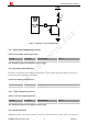


Table Of Contents
- Version History
- 1. Introduction
- 2. SIM2000S Overview
- 3. Package Information
- 4. Application Interface
- 4.1. Power Supply
- 4.2. Power on/down Scenarios
- 4.3. Power Saving Mode
- 4.4. Serial Port and Debug Interface
- 4.5. RI behaviors
- 4.6. Audio Interfaces
- 4.7. RUIM Card Interface
- 4.8. PCM Interface
- 4.9. Keypad Interface
- 4.10. I2C Bus
- 4.11. General Purpose Input/Output (GPIO)
- 4.12. ADC
- 4.13. PWM
- 4.14. Network Status Indication
- 4.15. NETLIGHT Multiplexing Function
- 4.16. Operating Status Indication
- 4.17. Antenna Interface
- 5. PCB Layout
- 6. Electrical, Reliability and Radio Characteristics
- 7. Manufacturing
- 8. Appendix

Smart Machine Smart Decision
SIM2000S_Hardware_Design_V1.00 41 2014-02-27
A typical recommended circuit of the PWM driver buzzer is shown in the following figure.
MODULE
4.7K
47K
VBA
T
PWM
Figure 36: Reference circuit of PWM driver buzzer
Table 32: Buzzer output characteristics
Parameter Min Typ Max Unit
Output voltage 2.85 V
Output current 6 mA
Note: PWM pin must be kept at low power level when module is in the power on procedure.
4.14. Network Status Indication
Table 33: Pin definition of the NETLIGHT
Pin name Pin number Description
NETLIGHT 52 Network Status Indication
The NETLIGHT pin can be used to drive a network status indication LED. The status of this pin is listed in
following table:
Table 34: Status of the NETLIGHT pin
Status SIM2000S behavior
Off SIM2000S is not running
64ms On/ 800ms Off SIM2000S not registered the network
64ms On/ 3000ms Off SIM2000S registered to the network
Reference circuit is recommended in the following figure: