
Hardware Design V1.00

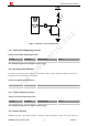


Table Of Contents
- Version History
- 1. Introduction
- 2. SIM2000S Overview
- 3. Package Information
- 4. Application Interface
- 4.1. Power Supply
- 4.2. Power on/down Scenarios
- 4.3. Power Saving Mode
- 4.4. Serial Port and Debug Interface
- 4.5. RI behaviors
- 4.6. Audio Interfaces
- 4.7. RUIM Card Interface
- 4.8. PCM Interface
- 4.9. Keypad Interface
- 4.10. I2C Bus
- 4.11. General Purpose Input/Output (GPIO)
- 4.12. ADC
- 4.13. PWM
- 4.14. Network Status Indication
- 4.15. NETLIGHT Multiplexing Function
- 4.16. Operating Status Indication
- 4.17. Antenna Interface
- 5. PCB Layout
- 6. Electrical, Reliability and Radio Characteristics
- 7. Manufacturing
- 8. Appendix

Smart Machine Smart Decision
Figure 37: Reference circuit of NETLIGHT
4.15. NETLIGHT Multiplexing Function
Table 35: NETLIGHT multiplexing function
Pin name Pin number Mode 0(default) Mode 1
NETLIGHT 52 NETLIGHT GPIO31
Note: Multiplexing function need different software supply.
4.16. Operating Status Indication
The pin66 is for operating status indication of the module. The pin output is high when module is powered on,
and output is low when module is powered off.
Table 36: Pin definition of the STATUS
Pin name Pin number Description
STATUS 66 operating Status Indication
4.16.1 STATUS Multiplexing Function
Table 37: STATUS multiplexing function
Pin name Pin number Mode 0(default) Mode 1
STATUS 66 STATUS GPIO32
Note: Multiplexing function needs different software supply.
4.17. Antenna Interface
SIM2000S provides a RF antenna interface. Customer’s antenna should be located in the host board and
SIM2000S_Hardware_Design_V1.00 42 2014-02-27