
Hardware Design V1.00

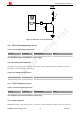


Table Of Contents
- Version History
- 1. Introduction
- 2. SIM2000S Overview
- 3. Package Information
- 4. Application Interface
- 4.1. Power Supply
- 4.2. Power on/down Scenarios
- 4.3. Power Saving Mode
- 4.4. Serial Port and Debug Interface
- 4.5. RI behaviors
- 4.6. Audio Interfaces
- 4.7. RUIM Card Interface
- 4.8. PCM Interface
- 4.9. Keypad Interface
- 4.10. I2C Bus
- 4.11. General Purpose Input/Output (GPIO)
- 4.12. ADC
- 4.13. PWM
- 4.14. Network Status Indication
- 4.15. NETLIGHT Multiplexing Function
- 4.16. Operating Status Indication
- 4.17. Antenna Interface
- 5. PCB Layout
- 6. Electrical, Reliability and Radio Characteristics
- 7. Manufacturing
- 8. Appendix

Smart Machine Smart Decision
connected to module’s antenna pad through micro-strip line or other type of RF trace and the trace impedance
must be controlled in 50. SIMCom recommends that the total insertion loss between the antenna pad and
antenna should meet the following requirements:
● CDMA 450MHZ<0.5dB
To facilitate the antenna tuning and certification test, a RF connector and an antenna matching circuit should be
added. The following figure is the recommended circuit.
59
MODULE
SIM2000S_Hardware_Design_V1.00 43 2014-02-27
R2
C1
60
RF_ANT
GND
C2
61
GND
R1
Antenna feed pad
Matching circuit
RF test connector
J1
J2
Figure 38: Antenna matching circuit
In this figure, the components R1,C1,C2 and R2 are used for antenna matching, the value of components can only
be got after the antenna tuning, usually, they are provided by antenna vendor. By default, the R1, R2 are 0 ohm
resistors, and the C1, C2 are reserved for tuning.
The RF test connector in the figure is used for the conducted RF performance test, and should be placed as close
as possible to the module’s antenna pin. The traces impedance between components must be controlled in 50ohm.