OWNER’S MANUAL Submersible Sump Pumps ® 293 Wright St., Delavan, WI 53115 Phone: 1-800-468-7867 1-800-546-7867 Fax: 1-800-390-5351 NOTICE D’UTILISATION Pompes de puisard submersible MANUAL DEL USUARIO Bombas sumergible de sumidero MOD.
Safety 2 READ AND FOLLOW SAFETY INSTRUCTIONS! Carefully read and follow all safety instructions in this manual and on pump. This is the safety alert symbol. When you see this symbol on your pump or in this manual, look for one of the following signal words and be alert to the potential for personal injury. warns about hazards that will cause serious personal injury, death or major property damage if ignored.
General Information / Installation 14. Protect the electrical cord from sharp objects, hot surfaces, oils, and chemicals. Avoid kinking the cord. Replace or repair damaged or worn cords immediately. 15. Do not touch an operating motor. Motors can operate at high temperatures. 16. Do not handle the pump or pump motor with wet hands or when standing on a wet or damp surface, or in water. INSTALLATION 1.
Installation / Electrical / Operation 5. Power Supply: These pumps are designed for 115 V., 60 Hz., operation and require a minimum 15 amp individual branch circuit. Both the pump and switch are supplied with 3-wire cord sets with grounding-type plugs. The switch plug is inserted directly into the outlet and the pump plug inserts into the opposite end of switch plug. Hazardous voltage. Can shock, burn or cause death. Pump is supplied with a grounding conductor and grounding-type attachment plug.
Operation / Maintenance / Troubleshooting To Replace the Vertical Float Switch: NOTICE: The float must be able to complete its entire cycle without interference from any other object. 1. Mount the bracket on the switch housing with the bracket mounting screws. See Figure 2. Switch Housing Pin 5 2. Mount the float and the float rod stop on the rod. 3. Slide the rod up through the bracket and into the slot in the bottom of the switch housing. Fasten the rod into the switch housing with the pin.
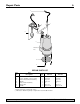
Repair Parts 6 1 7 2 3 4 5 Anti-airlock hole 6 2 REPAIR PARTS LIST Key No. 1 2 3 4 5 6 7 Part Description Power Cord Screws, Handle, Screen, Clamp Vertical Float Switch Assembly Adapter Cover, Motor Assembly Inlet Screen Handle Qty. 1 5 1 1 1 1 1 2957-01 227-264-B-TSU 670-646 Pkg 208 229-014 ** 667-013 383-147-B 2957-03 227-264-B-TSU 670-646 Pkg 208 229-014 ** 667-013 383-147-B ** If the motor fails, replace the pump. ( ) Indicates a different quantity is required for each model number.
Sécurite 7 LIRE TOUTES CES INSTRUCTIONSET LES SUIVRE! Lire attentivement toutes les consignes de sécurité contenues dans cette Notice et collées sur la pompe. Ce symbole indique qu’il faut être prudent. Lorsque ce symbole apparaît sur la pompe ou dans cette Notice, rechercher une des mises en garde qui suivent, car elles indiquent un potentiel de blessures corporelles : avertit d’un danger qui causera des blessures corporelles, la mort ou des dommages matériels importants si on l’ignore.
Renseignements généraux / Installation 14. Protéger le cordon électrique de la pompe contre les objets tranchants, les surfaces chaudes, l’huile et les produits chimiques. Éviter de tortiller le cordon électrique. Le remplacer ou le réparer immédiatement s’il est usé ou endommagé. 15. Ne pas toucher au moteur de la pompe pendant qu’elle fonctionne. Les moteurs peuvent fonctionner par des températures élevées. 16.
Installation / Electricité / Fonctionnement 5. 6. 7. Courant électrique : Ces pompes sont conçues pour fonctionner sur le courant alternatif de 115 volts, 60 Hz; elles doivent être branchées sur un circuit séparé ayant une intensité minimale de 15 ampères. La pompe et l’interrupteur à flotteur sont munis de cordons à 3 conducteurs, eux mêmes munis d’une fiche de mise à la terre.
Fonctionnement / Entrentien / Recherche des pannes 2. 3. Pour remplacer un interrupteur à flotteur vertical : NOTA : Le flotteur doit pouvoir se déplacer sur tout son arc sans être gêner d’autres objets. 1. À l’aide des vis de fixation, poser le support sur le boîtier de l’interrupteur. Se reporter à la Figure 2. boîtier du flotteur; sinon la pompe ne s’arrêtera pas de fonctionner. NOTA : Tirer prudemment sur la tige pour s’assurer qu’elle ne puisse pas se détacher du boîtier de l’interrupteur. 4.
Pièces de rechange 11 1 7 2 3 4 5 Clapet antibouchon Anti-airlock hole d’air 6 2 LISTE DE PIÈCES DE RECHANGE Réf.
Seguridad 12 LEA Y OBSERVE LAS INSTRUCCIONES DE SEGURIDAD Lea con atención y siga todas las instrucciones de seguridad que aparecen en este manual y en la bomba. Este es un símbolo de alerta de seguridad.
Información General / Instalación 14. Proteja el cordón eléctrico de objetos afilados, superficies calientes, aceites y sustancias químicas. Evite que el cordón se tuerza. Reemplace o repare inmediatamente todo cordón averiado o gastado. 15. No toque un motor en funcionamiento. Los motores pueden funcionar a altas temperaturas. 16. No maneje la bomba, el motor de la bomba, ni cambie los fusibles con las manos mojadas o cuando esté parado en suelo húmedo o mojado, o en el agua. INSTALACIÓN 1.
Instalación / Electridad / Operación 5. Suministro de corriente eléctrica. Estas bombas han sido diseñadas para funcionar a 115V, 60 Hz.y requieren un ramal individual de 15 amperios como mínimo. Tanto la bomba como el interruptor vienen con un juego de cordón trifilar y enchufe con puesta a tierra. El enchufe del interruptor se inserta directamente en el tomacorriente y el enchufe de la bomba se inserta en el extremo opuesto del enchufe del interruptor. Tensión peligrosa.
Operación / Mantenimiento / Localización de fallas Cómo reemplazar el interruptor de flotador vertical: AVISO: El flotador debe poder completar todo su ciclo sin interferencia de objeto alguno. 1. Monte el soporte en la caja del interruptor con los tornillos del soporte de montaje. Ver figura 2. Caja del Switch interruptor Housing Pasador Pin (pin) Soporte Bracket PRECAUCIÓN Verifique que el pasador sostenga la varilla del flotador en la caja del interruptor, de lo contrario la bomba no va a cerrar.
Piezas de repuesto 16 1 7 2 3 4 5 Válvula Anti-airlock anti bolsas holede aire 6 2 LISTA DE PIEZAS DE REPUESTO Clave No. 1 2 3 4 5 6 7 Descripción de la pieza Cordón eléctrico Tornillos, mango, criba, abrazadera Unidad de interruptor de flotador vertical Adaptador Tapa, unidad del motor Criba de admisión (inlet screen) Mango Cant.