
Owner`s manual


For parts or assistance, call Simer Customer Service at 1-800-468-7867 / 1-800-546-7867
Installation 4
SPECIFICATIONS
Power Supply Required. ...................................115 Volts
Motor Duty ...................................................Continuous
Circuit Requirement (minimum) .....................15.0 Amps
Discharge Adapter .......................................................1”
SHALLOW WELL JET PUMP
INSTALLATIONS:
• Have a vertical depth of 25’ or less.
• Have one pipe from the well to the pump case.
• Can be installed in a bored or drilled well, or in a
driven well.
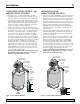
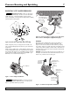
REPLACING AN OLD PUMP
Hazardous voltage. Can shock, burn or
kill. Disconnect power to pump before working on
pump or motor.
1. Drain and remove the old pump. Check the old pipe
for scale, lime, rust, etc., and replace it if necessary.
2. Install the pump in the system. Make sure that all
pipe joints in the suction pipe are air-tight as well as
water tight. If the suction pipe can suck air, the
pump will not be able to pull water from the well.
3. Adjust the pump mounting height so that the plumb-
ing connections do not put a strain on the pump
body. Support the pipe so that the pump body does
not take the weight of piping or fittings.
You have just completed the well plumbing for your
new shallow well jet pump. Please go to Page 6 for
discharge pipe and tank connections.
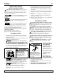
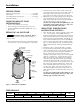
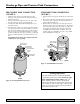
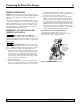
WELL POINT (DRIVEN POINT)
INSTALLATION (FIGURE 1)
1. Drive the well, using “drive couplings” and a “drive
cap”. “Drive fittings” are threaded all the way
through and allow the pipe ends to butt against each
other so that the driving force of the maul is carried
by the pipe and not by the threads. The ordinary fit-
tings found in hardware stores are not threaded all
the way through the fitting and can collapse under
impact. “Drive fittings” are also smoother than stan-
dard plumbing fittings, making ground penetration
easier.
2. Mount the pump as close to the well as possible
3. Use the fewest possible fittings (especially elbows)
when connecting the pipe from the well point to the
pump suction port. The suction pipe should be at
least as large as the suction port on the pump
(include a check valve if your pump is not equipped
with one – see Figure 1). Support the pipe so that
there are no dips or sags in the pipe, so it doesn’t
strain the pump body, and so that it slopes slightly
upward from the well to the pump (high spots can
cause air pockets which can air lock the pump). Seal
the suction pipe joints with teflon tape. Joints must
be air and water tight. If the suction pipe can suck
air, the pump cannot pull water from the well. If
one well point does not supply enough water, con-
sider connecting two or three well points to one suc-
tion pipe.
You have just completed the suction piping for your
new shallow well jet pump. Please go to Page 6 for
discharge pipe and tank connections.
Output Pressure Maximum
Model 0 10 20 30 40 50 PSI
2825ss 10 8.5 8.0 7.5 7.0 6.0 80
PERFORMANCE
Not
to
Scale
Pump Priming
Tee and Plug
3938 0401
To Household
Water System
Suction Pipe
From Well
Drive
Coupling
Drive
Point
Check
Valve
Priming
Tee and
Plug
Figure 1 – Driven Point Installation