
User Manual


SGD-SB2025NT-TUM, Part 2
Jan 12 Page 25
NI ET
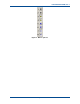
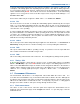
Figure 13. Environment I/O.
2.5.2 Indicators
Each connection point is able to operate as an input or an output, which is defined by the
configuration mode for each connection (see
Section 5.2.4 – Environment
). Inputs are denoted
by a circular indicator and outputs by a square indicator. An active input or output is shown by the
corresponding indicator being lit
Yellow
as seen in
Figure 13
above. Each connection has
provision for a user entered text label alongside the indicator (see
Section 5.2.4.1 – Status
).
2.6 NI
B
UTTON
A
REA
An overview of the functions of each button on the NI ET main page is provided in the sections
below. Full details of the operation of each will be covered under
Section 5 Solar
Commissioning.
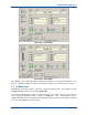
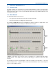
Figure 14. NI ET Buttons.
2.6.1 Network
The ‘Network’ button opens the window where the IP address of the NI is entered – see
Section
4.2 – Setting the NI IP Address
for full details. This facility is only available to the NI ET.
2.6.2 Eng (Engineering)
Selecting the ‘Eng’ button opens a new window that has four pages of information: ‘Main Audio’,
‘Signalling’, ‘Facilities’ and ‘Environment’. Each page is accessed by selecting the corresponding
tab – see
Section 5.2 – NI Engineering
for details of each. The results are identical to those
obtained on the TM ET view of the NI.
2.6.3 DSP
The ‘DSP’ button is used if new firmware is to be loaded into the DSP – see
Section 11.2.5 – NI
DSP Firmware Up-issue
for full details. This facility is only available to the NI ET.
2.6.4 GPS
If the 1PPS timing signal is being supplied from a GPS receiver that also has NMEA data output;
e.g. Dalman 60742, the ‘GPS’ button opens a window where information about the satellites and
the received signal levels is displayed. If no NMEA data is available then the window will be
devoid of information.