
User Manual


SGD-SB2025NT-TUM, Part 2
Jan 12 Page 30
TM ET
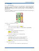
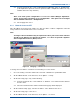
3.4.1.3 Facility Key
A normal operating state is indicated by the status indicator being lit
Green
, an abnormal state by a
status indicator being lit
Red
. See
Section 9.2 – Facility Key
for full details.
3.4.1.4 Network
See
Section 4.3 – Setting the TM IP Address
for full details.
3.4.1.5 Eng
See
Section 5.3 – TM Engineering
for full details.
3.4.1.6 GPS
See
Section 9.1 – GPS
for full details.
3.4.1.7 Relations
See
Section 6 – Solar Channels (Relations)
for full details.
3.4.1.8 Logging
See
Section 13 – TM Logging
for full details.
3.4.1.9 List
The ‘List’ feature is an aid for the user as opposed to a commissioning tool. It presents the user
with a window giving a list of ‘System Names’, i.e. those given to every NI and channel on the TM.
Whist this is available as a discrete function from the ‘List’ button, it is most useful when the
‘Relations’ function is used and can be accessed directly from that page. It is therefore described
in greater detail in
Section 6 – Solar Channels (Relations)
.
3.4.1.10 Chan View
See
Section 6.3 – Channel View Facility
for full details.
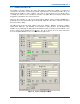
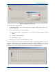
3.4.2 Channel Status Panel
To select the status window for Channel #N (where N is the number of the required channel), click
‘Chn:’ N tab (indicated in
Figure 19
below). The tab will gain a
Green
highlight when selected as
does the Station Interface panels of all member sites of this Channel (see
Section 3.3.1 – Station
NI Panels
). If a Central NI has been assigned to operate this Channel, the tab for that unit will also
gain the
Green
highlight. The example in
Figure 19
shows Channel #1 selected, which is
operated by Central NI #1.
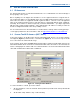
Functions and facilities accessed using the ‘Setup’ button are covered in
Section 5.4 – Channel
Setup
.
Figure 19. Channel #1 Status Panel.