
User Manual


SGD-SB2025NT-TUM, Part 2
Jan 12 Page 36
SOLAR CONFIGURATION
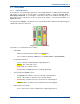
Configuration can now continue as for a local connection. However, it will not be possible to
change any of the IP parameters of the TM itself whilst connected in this way but this information
will be displayed when the TM ‘Network’ button is clicked.
4.4 TM
A
DDRESS
I
NVENTORY
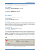
The next stage is to inform the TM of all the NIs that will operate within the Solar network.
Therefore, the IP address of every NI must be known, if not actually programmed into the NI units
although that is preferable.
4.4.1 TM Capacity
A Solar network can be populated by a maximum of 32 NIs operating in Station mode. Depending
upon the configuration options purchased, the Solar P25 network may comprise of multiple
channels up to a maximum of 4 and a maximum of 4 NIs operating in Central mode. One channel
may support the maximum of 32 Station NIs and may be permitted to have more than one Central
NI per channel (this is a factory configured option).
If the PMR system is only required to work in T/T (repeat) mode, a Central NI it is not necessary
(there being no Console or Control Room). Every NI will be assigned a unique system ‘Address’:
Central NIs will range from CEN1 to CEN4; and Stations from STN1 to STN32 – these numbers
are crucial for the multi-channel option.
4.4.2 Allocating NI
It is important to understand that the action of entering the IP address for each and every NI into
the TM’s system address inventory defines the mode of operation of each NI unit within the
system. Furthermore, the settings stored in the TM for the NI relate to the system address and not
to the individual unit’s IP address. It is the system address that is used to allocate stations and
centrals to channels in the multi-channel version.
Whilst the same IP address should not be entered in more than one place in the system, this is not
an illegal action. However, an attempt to ‘Enable’ a second use of the same IP address on the
system will be rejected.
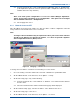
4.4.3 Allocating a Station NI
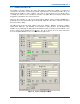
The upper area of the TM ET main window shows 32 blank station panels, which relate to the 32
possible Station NI (radio base stations) in the Solar network. These will show the status of each
Station NI member as they are connected.
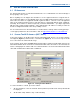
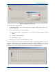
This process would logically start at #1 and increment in order, however, this is not mandatory, as
any Station NI may be assigned to any station panel. For a multi-channel system, there is merit in
arranging the stations in groups with unassigned panels between them, which makes the channel
separation more obvious.
Figure 25
overleaf shows a NI being allocated to Station #1 (station panel #1).