
User Manual


SGD-SB2025NT-TUM, Part 2
Jan 12 Page 50
SOLAR COMMISSIONING
Note.
For FW Config builds other than the standard 0x7FFF, the Auto modes may produce a
different operation to that shown in Table 1. See Section 15 – Firmware Extensions for
more information.
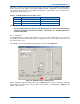
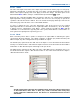
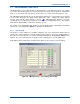
5.2.2.5 Isolated Outputs
Control of the isolated outputs (relays) and their current state is presented on the ‘Status’ page
(this is the default view) and configured on the ‘Mode’ page. The Isolated Outputs ‘Status’ page
and ‘Mode’ page are shown below in
Figure 43
.
Figure 43. Isolated Output Options.
Each output is assigned to either a ‘Manual’ mode, which allows manual control of the output relay
or an ‘Auto’ mode, which pre-defines the duty of the output relay as shown overleaf in
Table 2
.
Once assigned to either of the two auto modes, the button to manually activate the output
becomes unavailable (greyed out).
The ‘(Inv)’ option of each setting inverts the “ON” state of the output with respect to the button
state; i.e. in non-inverted mode the output is “ON” when the button is ‘IN’, in the inverted mode the
output is “ON” when the button is ‘OUT’.
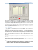
To change the mode of an output, carry out the following:
1. On the ‘NI Engineering’ window, select the ‘Eng’ button (IN).
2. On the ‘Signalling’ page, select the ‘Isolated Outputs – Mode’ tab to access the ‘Mode’ page.
3. On the ‘Mode’ page, for the output in question, using the drop-down list, select the mode
required.
Note.
On the Isolated Outputs Status page, there is provision for the user to enter a text
label of choice against each output as a reminder of the role assigned to the output.
4. On the ‘Signalling’ page, select the ‘Isolated Outputs – Status’ tab to access the ‘Status’
page.
5. On the ‘Status’ page, for the Output in question, click in the text box and enter or amend the
text as required.
6. On the ‘NI Engineering’ window, select the ‘Apply’ button.