
User Manual


SGD-SB2025NT-TUM, Part 2
Jan 12 Page 55
SOLAR COMMISSIONING
5.2.4.1 Status
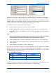
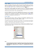
The state of the inputs and control of the outputs is presented on the ‘Status’ page for each group,
which is the default view. To change the state of an output, select the ‘Eng’ button (IN), select the
button of the required output(s) then select ‘Apply’ to invoke the change. The inner square of the
button will turn
Blue
until the change is confirmed whereupon it will turn
Grey
again.
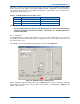
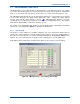
Each item has a text label available that is designed to help the user confirm that the individual
input/output that is being examined or controlled is the correct one; the text plays no part in the
operation of the unit and can be omitted. The text entered via this page will be presented on the
main status page of the NI and on some of the TM ET windows.
To enter or change the text, select the ‘Eng’ button, click in the text box for the required
input/output and enter or amend the text as required (the limit is 20 characters). As for all settings,
a change must be completed by using ‘Apply’. At this point the text will turn
Blue
until full
confirmation is received from the opposing end of the system, which will take several minutes as
text is given lowest priority in the supervisory process.
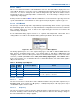
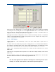
5.2.4.2 Mode
Each connection point is able to operate as an input or an output, which is defined by the option
selected from the drop-down list. The setting of ‘Monitor’ or ‘Monitor (Inv)’ dictates that the point
will be an input; any other setting dictates the point will be an output.
The ‘Monitor (Inv)’ option inverts the “ON” state of the input; i.e. in non-inverted mode the indicator
and any associated function is “ON” when the input is taken low, in the inverted mode the indicator
and function is “ON” when the input is taken high or left open circuit.
The ‘Manual (Inv)’ option inverts the “ON” state of the output with respect to the button state; i.e. in
non-inverted mode the output is “ON” when the button is “IN”, in the inverted mode the output is
“ON” when the button is “OUT”.
Figure 49. Environment Mode settings.
Note.
For FW Config builds other than the standard 0x7FFF, whilst the indicator will function
as described above, when ‘Auto’ or ‘Auto (Inv)’ mode is selected, either setting may
invoke a different or additional action. See Section 15 – Firmware Extensions for more
information.