
User Manual


SGD-SB2025NT-TUM, Part 2
Jan 12 Page 74
DIAGNOSTICS
2.5. Repeat Paras 2.3 and 2.4 for any further Primary TMs but ticking ‘IP Address’ box 2, 3
etc in order of their priority.
2.6. Select the ‘Apply’ and then the ‘Close’ buttons.
Note.
The IP address table also reflects the priority order in which the Secondary TM will
take over from the Primary TM (highest priority is position 1, lowest priority is
position 5).
The ‘Duplication Status’ text will now change to reflect the duplication setting and the colour of the
indicator will show the status – see
Section 8.2.4
below. Once the Secondary TM is configured
and connected to the network it will quickly gain the configuration(s) from the Primary TM(s) and be
ready to operate as hot standby.
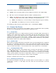
8.2.4 Duplication Status
The text alongside the Status indication on the TM Status panel will show ‘Primary’ or ‘Secondary’
according to the duplication configuration.
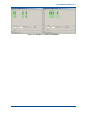
Figure 65. Duplication Status Indication.
Confirmation that Primary and Secondary units are operating and in communications with each
other is shown by the ‘Duplication Status’ indicator going
Green
; loss of communications will cause
the indicator to turn
Red
on both units. A
Red
Status indication does not necessarily mean that the
other TM has failed but that there is no information exchange between units. This may result from
unit failure or a network problem. However, in the case where the Secondary TM has taken over
from another Primary TM since it no longer is able to offer support to those of a lower priority, the
Secondary TM will cease communications with those units causing a
Red
Status indication to be
displayed on each.
The Status indicator may be assigned ‘Alarm’ status although an unduplicated TM will never show
a
Red
Status indication; see
Section 12 – Alarms
.