
User Manual


SGD-SB2025NT-TUM, Part 2
Jan 12 Page 86
ALARMS
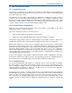
12.3.1 Environment Inputs
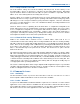
Each of the environment inputs may be selected to generate an alarm whenever that input is taken
to an active state. As each on the sixteen connection points may be defined as an input or an
output, only those defined as inputs are available to assign to an alarm; those defined as outputs
do not support the alarm facility as shown by the button being unavailable.
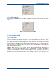
As an example,
Figure 72
below shows that points 4, 5 and 6 in Group 1 and 3, 4, 7 and 8 in
Group 2 have been defined as outputs making them unavailable to be assigned to the alarm state.
The remaining points have been defined as inputs and, of these, 2 and 7 in Group 1 and 1 and 6 in
Group 2 have been assigned to alarm status.
Figure 72. Setting Alarms for Environment Inputs on a NI.
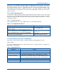
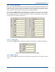
12.3.2 Isolated Inputs
As an example,
Figure 73
below shows that ‘Isolated Input’ #3 has been assigned to alarm status.
Figure 73. Setting Alarms for Isolated Inputs on a NI.
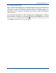
12.3.3 NI Misc Alarms
As an example,
Figure 74
overleaf shows that ‘Network’ and ‘PPS’ have been assigned to alarm
status.