
User Manual


SGD-SB2025NT-TUM, Part 1
Jan 12 Page 15 INSTALLATION & OPERATION
3 INSTALLATION AND OPERATION
3.1 I
NSTALLATION
SB2025 series radios are securely packed for transport with special moulded packers within a
pasteboard container. Before unpacking the SB2025 radio, please inspect the packaging for signs
of damage and report any damage to your SB2025 distributor.
Upon unpacking of the SB2025 radio, please ensure that all items shipped were received, report
any missing items to your SB2025 distributor.
All ports on the rear of the radio should be carefully examined to ensure that packaging has not
become wedged inside them. It is very important to examine the fan as operation of the radio will
be affected if any packaging or shipping damage causes the fan to stop working.
If you intend to install the radio in an equipment rack consult the supplier’s instructions for your
system. Simoco recommends that the radio be secured into the rack system using four screws
through the mounting holes in the front panel and supported on a rack shelf. If the radio is to be
used in a stand-alone configuration, ensure that it is in a secure, dry location with sufficient air
space around it to allow for adequate ventilation.
It is recommended that the chassis is earthed to the equipment rack. A grounding screw terminal
is provided on the left side of the main chassis for connection to the site ground point (Protective
Earth). The wire is terminated with a closed loop ring terminal (eyelet) connector which is fixed to
the earthing screw with a lock washer to stop them working loose. It is important that the earth
wire connector is located at bottom, closest to the chassis.
The earthing conductor should be connected to the best possible earth, such as an earthed
mounting plate or an earth rod. Remember that the earthing conductor must be as short as
possible and lowest resistance typically <0.1 Ω.
It is recommended to protect the Base Station from lightning, by using a lightning arrestor. There
are many publications covering antennas and their installation. Consult with your local dealer for
more information and recommendations.
Equipment connection details are located in Section 4. The SB2025 will draw approximately 10 A
(band dependent) on transmit and the gauge of the DC cable fitted to the 12 V supply connector
should be adequate to ensure less than 0.5 V volt-drop at this current. To maintain compliance
with Radio and Telecommunications Terminal Equipment (R&TTE) (CE) approval, the DC cable
length should not exceed three metres.
Note.
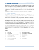
The SB2025 contains No reverse polarity protection. Ensure both the positive (red)
and negative (black) terminals are correctly connected and an inline 15 Amp fuse is
fitted on the Positive wire. See example in picture below (Not include).
Fuse Link
15Amp Fuse
In lin e F use
Holder