
User Manual


SGD-SB2025NT-TUM, Part 1
Jan 12 Page 17 INSTALLATION & OPERATION
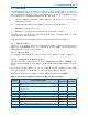
Jumper Function/Description
Default
Selection
Default
Position
JMP10 Controls the direction of the RS-232 Tx and Rx data. Swap 2-3
JMP11 Controls the direction of the RS-232 Tx and Rx data. Swap 2-3
JMP12 No effect in SB2025. 1-2
JMP13 No effect in SB2025. 1-2
JMP14 No effect in SB2025. 1-2
JMP15 No effect in SB2025. 2-3
JMP16 No effect in SB2025. 2-3
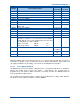
JMP17
Selects the Mute/Squelch output polarity to either normally
high or low.
Active low 1-2
JMP18 No effect in SB2025. Active low 1-2
JMP19 No effect in SB2025. Pull up 2-3
JMP22 No effect in SB2025. Low gain Not fitted
JMP23 No effect in SB2025. Disabled Not fitted
JMP24 No effect in SB2025. 1-2
Mute defeat enable. Mute defeat cannot be used if RX
TALK line is required. To use mute defeat remove JMP12
and fit JMP 25. The control signal polarity can be inverted
by changing the position of JMP25.
Active low control: JMP25 2-3
JMP25
Active high control: JMP25 1-2
Disabled Not fitted
JMP26 CTCSS O/P / Tx VF Loopback control
Tx VF
Loopback
2-3
JMP27 CTCSS I/P / WB DCFM I/P
WB DCFM
I/P
2-3
T99 Option Link IN
When the SB2025 option card is not fitted, there is no connection made to SKK (Aux 2 connector)
on the Micro Controller. Links should be placed across SKK1-2 (Discriminator audio), SKK11-12
(Tx supply) and SKK13-14 (Rx supply). These links are normally fitted in production.
3.2.2.2 Select Operating Mode
The SB2025 can operate in a number of different modes. The primary alternatives are full duplex,
which is the default mode, repeater and simplex. Using MxTools, the operating mode is
programmed for each channel. When a channel is selected in operation, the SB2025 adopts the
mode programmed for that channel.
The operating mode programmed in the software can be modified by the settings of DIP Switch 2.
The functions of this switch are detailed overleaf in Table 5.