
User Manual


SGD-SB2025NT-TUM, Part 1
Jan 12 Page 24 GENERAL DESCRIPTION
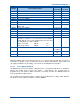
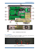
Table 9. Rear Panel Connections.
Connector #
Conn Type
Function Description
CN5 3 PIN DC Power I/P
13.8 V DC power I/P. Also +28 V I/P on spare
pin if required.
CN6 N TYPE N type Rx I/P
N-Type connector can used for the I/P to the
Rx for full duplex operation.
CN7 BNC Rx I/P
Standard BNC connector for the 10 MHz High
Stability Oscillator I/P.
CN8 N TYPE Tx O/P
The RF power O/P from the Tx for full duplex
operation.
CN9 RJ45 Ethernet 10/100 base-T RJ45 Ethernet connector.
CN3
20-way
MDR-F
Environment I/O
Provided for monitoring and control of external
devices. Has 16 configurable I/Os.
CN1 DB15-F GPS 1PPS Timing
Provides the GPS interface, if required.
4.1.2.1 GPS (1PPS Timing Signal Input)
The 1PPS input can be accepted in either RS422 or TTL voltage format; the connections made to
this connector must match the input type and be correctly identified in the configuration
parameters. GPS National Marine Electronics Association (NMEA) data such as presented by the
Dalman GPS Rx 40762 will be displayed on the GPS page of the ET, however, this data input can
only be accepted in RS422 format.
4.1.2.2 Environment I/O
Integral to Solar is the provision for monitoring and control of external devices. All signals are
relative to ground and have voltage input and current switching limits. A low current 12 V supply is
also available from this connector to drive switching circuits (see Section 4.2 – Environment I/O
Overview).
4.1.2.3 DC Power Input
DC power is connected to the base station via this three pin male connector. For 50 W
transceivers, pins 2 and 3 are used for the 12 V DC pin 1 is unused. The DC input is fully isolated
from chassis and the equipment supply rails, making this option suitable for any supply earth
arrangement.
4.1.2.4 Transmitter Output
The Tx antenna connection on the SB2025 base stations is provided with a 50 Ω female N-type
socket.
The antenna cable connections must be made with 50 Ω N-types on flexible tails. The Voltage
Standing Wave Ratio (VSWR) of these connections should be tested prior to use by using of a
suitable test set, e.g. an Anritsu/Wiltron S331A. A good VSWR of 1.5:1 or better at the relevant Tx
and Rx frequencies should be ensured.
Mating connectors should be galvanically compatible with nickel outer and gold centre pin to
minimise passive intermodulation.
A minimum of 85 dB transmit-receive isolation should be provided by the antenna system and
associated filters.
It is recommended that a good quality flexible co-axial cable is used, e.g. with double-screening
braid and multi-strand copper inner.