
User Manual


SGD-SB2025NT-TUM, Part 1
Jan 12 Page 46 ALIGNMENT & TESTING
25.3. Adjust the ‘VCO Level (LF Audio)’ digital potentiometer to obtain 1.5 kHz deviation on
the Radio Test Set.
25.4. Select the ‘OK’ button to accept the changes made and close the Channel Edit screen.
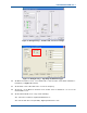
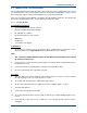
Figure 10. MxTools – Set Software Channel to tick button.
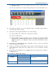
26. On the MxTools Channel screen, on the dynamic tool bar, select ‘Write Channel’ button to
save the changes made to the radio.
27. On the NI ET, on the Engineering window, carry out the following:
27.1. On the Facilities tab, set the Test Tone ‘Frequency’ to 200 Hz.
27.2. Select the ‘Apply’ button.
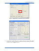
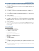
27.3. On the Facilities tab, check that the Test Tone ‘Frequency’ has changed to ‘MOD’
indicating that the SB2025 Modulation Balance test signal is being generated (see
Figure 11 overleaf). The SB2025 Tx will be keyed and modulated with a 200 Hz
square wave.
28. On the RTS, use a Wide Band AF Filter setting with a response of at least 15 kHz and
monitor the SB2025 Tx modulation.
29. On the PC, on the MxTools main window, on the tool bar, select the ‘Channel Info’ icon and,
on the channel table, double click on the channel in use to access the MxTools ‘Channel
Edit’ screen.
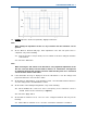
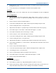
30. On the MxTools Channel Edit screen (see Figure 12 overleaf), adjust the various settings as
per Table 16 below.
Table 16. MxTools, Channel Edit Settings.
Area Setting Setting Required
TTR Channel
Simplex Channel
Scan Channel
All unchecked
RF Mode
Wide Band or Narrow Band As required (25 or 12.5 kHz bandwidth)
Frequency Settings
Tx Subtone (Hz) Disabled