
User Manual


SGD-SB2025NT-TUM, Part 1
Jan 12 Page 52 ALIGNMENT & TESTING
6.2 M
ODULE
L
EVEL
T
EST
P
ROCEDURES
The following alignment and testing procedures are based upon using a working transceiver as the
test environment. It is also assumed that test fixtures to the radio are available to exercise control
lines and monitor outputs and that a PC with MxTools is connected to the radio.
There are four modules in the SB2025 – the Exciter, Rx, PA and Micro Controller. The Exciter and
the Rx have VCO daughter boards. The Rx and Exciter VCOs are similar.
6.2.1 Exciter Module
Test Equipment Required:
• Tested SB2025NT with Exciter removed.
• Tested Tx VCO board (in wanted band).
• PC with MxTools software.
• RF Communications Test Set (CTS).
• Multimeter.
• Oscilloscope.
• +13.8 VDC Power Supply.
Preliminaries:
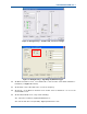
1. On the MxTools Channel screen, program the upper, middle and lower frequencies of the
frequency band (refer to Appendix A for band split details) into three channels.
Note.
The ‘Continuous Update Enabled’ option on the MxTools Channel Edit screen should
be selected for these tests.
2. Remove the top cover from Exciter module under test and fit a known working VCO tuned for
the band to be tested.
3. Connect the Exciter to a working Micro Controller via 16-way ribbon cable.
4. Disconnect Exciter RF drive output CN1 from PA.
Procedure
5. Switch on DC power and check that the output voltage on pin 1 of IC5 is 5 V ± 0.2 V and that
the output voltage on pin 1 of IC3 and IC8 is 8 V ± 0.2 V.
6. Assert PTT and check that 8 V is switched through to SKU-3.
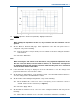
7. On the centre pin pad of CN3, check that the reference oscillator signal is >3 Vp-p.
8. Select the mid channel.
9. Connect the CTS RF input port to CN1.
10. Assert PTT and check that Lock Detect (LD) on SKD-16 goes high indicating that the loop is
locked.
11. Check that the power control volts on SKD-4 is >10 V and that the RF output on CN1 is
>300 mW.