
User Manual


SGD-SB2025NT-TUM, Part 1
Jan 12 Page 53 ALIGNMENT & TESTING
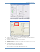
12. On the MxTools Channel Edit screen, adjust the ‘Tx RF Power’ digital potentiometer slider to
0 (zero) and check that the power control volts on SKD-4 drops to 0 V and that the RF power
out drops to <1 mW.
13. On the MxTools Channel Edit screen, set the the ‘Tx RF Power’ digital potentiometer slider
back to mid position.
14. Select the lowest channel.
15. Assert PTT and check that LD goes high and that the VCO tuning volts on SKD-14 is >2 V.
16. Select the highest channel.
17. Assert PTT and check that LD goes high and that the VCO tuning volts on SKD-14 is <18 V.
Check that the RF output in both cases is >300 mW.
18. Select the mid channel.
19. Assert PTT. Note the RF output carrier frequency.
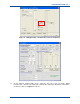
20. On the MxTools Channel Edit screen, check that, by adjusting the ‘Ref Osc Freq’ digital
potentiometer slider, the carrier frequency can be adjusted to ±3 ppm of the nominal
frequency.
21. Select the mid channel.
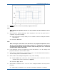
22. Assert PTT and carry out the Section 6.1.9 – Peak Deviation and Modulation Balance part
of the Tx VF alignment procedure to check the function of the VCO and Reference oscillator
modulation inputs.
6.2.2 Receiver Module
Test Equipment Required:
• Tested SB2025NT with Rx removed.
• Tested Rx VCO board (in wanted band).
• PC with MxTools software installed.
• RF Communications Test Set.
• Spectrum Analyser with Tracking Generator.
• Multimeter.
• High Frequency (89.545 MHz) Pick up Loop.
• Oscilloscope.
• +13.8 VDC Power Supply.
Preliminaries
1. On the MxTools Channel screen, program the upper, middle and lower frequencies of the
frequency band (refer to Appendix A for band split details) into three channels.
Note.
The ‘Continuous Update Enabled’ option on the MxTools Channel Edit screen should
be selected for these tests.