
Unit installation

Smart Relay: SREL, SREL.ZK, SREL.ADV
Page 10
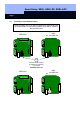
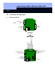
6.2 SREL.ADV
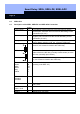
6.3 Description of the SREL, SREL.ZK and SREL.ADV Connection
Name
Symbol
Description
Power supply + / ~ If connecting a direct current (5 to 24 VDC) source, use the
positive pole, otherwise use one of the two alternating current
connections (12 VAC)
Power supply - / ~ If connecting a direct current (5 to 24 VDC) source, use the
negative pole, otherwise use the second alternating current
connection (12 VAC)
Battery Plug connection for a battery (when operating without a power
supply) Battery ordering code, incl. connector: SREL.BAT
NC relay Normally closed contact for the change-over relay. When not
acted on, this contact is closed to the COM relay
COM relay Common contact on the change-over relay. This contact is
either wired to the NC relay (normally closed contact) or to the
NO relay (normally open contact)
NO relay Normally open contact on the change-over relay. When acted
on, this contact is closed to the COM relay
External antenna
Brown
White
Green
Grey
Yellow
BN
WH
GN
GY
YL
Connection for the coloured cables of an extended antenna
(ordering code SREL.AV)
RS-485COM
RS-485A
RS-485B
C
A
B
Bus connection for external modules
+ Vaux +V Typically 3.0 - 5.0V +/- 0.5V for external LED’s or buzzer,
max. 10mA
LED/ Buzzer/
Input 1/ CLS
F3 Multifunction connection
Serial 1/ input 2 F2 Multifunction connection
Serial 2 F1 Multifunction connection