
Unit installation

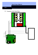

Smart Output Module
Page 5
3.0 Before Ordering
3.1 Smart Relay
At least one type SREL.ADV Smart Relay is necessary for operating a Smart Output
Module. Please read the Smart Relay Product Manual for information on ordering.
3.2 Determine the Number of Modules that are Needed
Up to 16 external modules can be connected to one type SREL.ADV Smart Relay. If
you select the "Signalling" option in the configuration, the number of outputs per
Smart Output Module is reduced from eight to four. Each module has a separate
configuration in the software.
3.3 Obtain and Dimension the Power Supply
The type SREL.ADV Smart Relay and up to eight type SOM8 external modules can
be operated with one power supply (SREL.NT). For the data regarding the power
supplies, take the technical specifications (currents, voltages and powers) of the
Smart Relay and the modules into consideration.
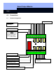
3.4 Determine the Installation Technique and the Installation Site
The modules are attached to DIN rails. The length of these DIN rails depends on the
number of modules that have to be attached next to one another. The Smart Relay
Advanced units are typically not mounted on DIN rails, but instead are installed at the
place where the transponders should be read.
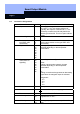
3.5 Cable Types and Paths
There should be enough room around a Smart Output Module to allow all cables to
be laid without kinking them too much. We recommend cable type IY(ST)Y (Twisted-
Pair, shielded cable), strand diameter 0.6 mm.
3.6 Outside Installation
A suitable IP 65 (SOM.IP65G) housing must be provided for outside installation.
3.7 Guidelines
The installation should be performed according to VDE guidelines, by experts who
have been