
Unit installation
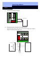
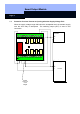

Smart Output Module
Page 13
8.0 Programming and Configuration
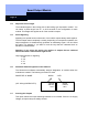
8.1 General Information
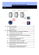
To program the Smart Output Module, connect it to a type SREL.ADV Smart Relay.
Supply power to both the Smart Relay and the Smart Output Module and hold the
programming device close to the Smart Relay. The Smart Output Module itself cannot
communicate with the Config Device.
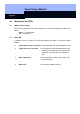
8.2 Enter the Number of Modules
Enter the number of connected Smart Output Modules in the Smart Relay
configuration. The largest possible value here is 16 modules. This automatically
creates lockings in the locking plan for each of a module's outputs.
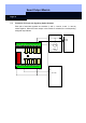
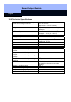
8.3 Select the Module Addresses
The Smart Relay communicates with each connected module over its address. This
address is set up in the Smart Output module using the address switches. The
following addresses are permitted:
Modul Adresse
Module 1 0 (default factory setting)
Module 2 1
Module 3 2
Module 4 3
Module 5 4
Module 6 5
Module 7 6
Module 8 7
Module 9 8
Module 10 9
Module 11 A
Module 12 B
Module 13 C
Module 14 D
Module 15 E
Module 16 F