
Unit installation

VdS Shunt lock function 3066
Page 12
The BAC must draw pin 29 to ground for the acoustic acknowledgement.
Jumper B2 is inserted:
⇒ Maximum transmitting range. For VdS-compliant installation, however, you
must then work with external keys to differentiate between outside and inside.
(refer to 4.3 VdS-Compliant Installation of the Activation Unit).
⇒ In VdS-compliant installation, the range of the antenna extender is reduced
solely by the correct use of the aluminum sleeve. (Refer to 4.3 VdS-Compliant
Installation of the Activation Unit).
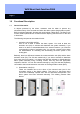
Install the activation unit so that the distance between its antenna and other digital
components is
at least 1 m (40 inches).
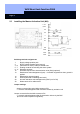
2.3.1 Testing the Master Activation Unit (MA):
Before final installation, apply voltage to contacts 1 and 2 of the activation unit
(compound battery). Make sure that the polarity is correct. Do not wire the other
contacts for this test.
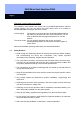
Transponder
master activation unit 1 cm to max. 3 cm (.4 to 1.2 inches)
L This corresponds to the strongly reduced range when the screening sleeve is
inserted on the antenna extender (refer to Chap. 4.3).
Make sure that all components are correctly programmed (refer to Chap. 3). Insert
jumper B1 on the right. Then test whether the relay on the activation unit switches
(soldering terminals 5 and 7) by operating the transponder two times in quick
succession (within 0.5 ... 2 sec.).
An acoustic signal indicates the switching state of the alarm system. A 2.5-second
long continuous tone signals that the activation contact was closed and a two-part
signal tone (short – long) means that the activation contact is open again (de-
activated).
Then you must convert the acoustic activation acknowledgement to BAC operation
(insert jumper B1 to the left) and test it by attempting to activate the system. Once the
master activation unit has successfully passed the test, you can carry out the actual
permanent installation.
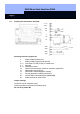
2.3.2 Connecting Power Supply, Switch Contacts and Sabotage Contacts:
• Power supply
Connect the positive pole of a direct current source between +8 ... + 16 V
(recommended: +12 V) to soldering terminal 1. Note that the voltage is not permitted
to
exceed a value of
+16 V under any circumstances
Connect soldering terminal 2 to ground