
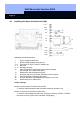
Unit installation

VdS Shunt lock function 3066
Page 16
• Switch contacts
Soldering terminal 5 to 7 are not needed for the slave activation unit unless you want
to use the SA for internal activation. In this case, wire the SA separately from other
activation units. Connect soldering terminals 5 to 7 to the internal activation
connection of the BAC. Refer to the BAS installer instructions for wiring information.
• Sabotage contacts
Connect them to soldering terminals 8 to 11. Solder the Rs resistor (terminating
resistor or short circuit) to soldering pins X27 and X28 (refer to the drawing).
• Optional local activation suppression
If you want to use activation suppression, connect a floating contact between
soldering terminals 12 and 15. When the contact is closed, it is impossible to activate
or deactivate the system locally (from this SA). This has no effect on the activation
behavior of other activation units.
2.4.3 Connecting Deactivation Acknowledgement and Activation Request
Refer to Chapter 2.5.
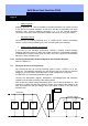
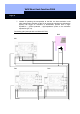
2.5 Wiring the Shunt Lock Components
We recommend that you use the following types of lines: J-Y(ST)Y 6 or 8 pin,
Ø 0.6 mm. The diameter should be fit to the length of the line so that the minimum
voltage for the components never falls below +8 volt (voltage drop on the line).
ATTENTION: You should always shield longer lines.
Connect the deactivation request, deactivation acknowledgement and activation
request to one another according to the drawing below.
Also connect the supply voltage everywhere (pins 1 and 2, with the positive on 1 and
ground on 2). Make sure that the polarity is correct. Then measure the voltage on all
units and make sure that the voltage never falls below a value of +8v and never
exceeds +16V.
Pin 12 Pin 13 Pin 13 Pin 13 Pin 13 Pin 13 Pin 13
Pin 14 Pin 14 Pins 5,7 Pin 14 Pin 14 Pin 14 Pin 14
Activation re
q
uest
Deactivation
r
e
q
uest
Deactivation
DA DA DA
MA SA SA
BAC