
Unit installation

VdS Shunt lock function 3066
Page 26
4.3 VdS-Compliant Installation of the Activation Unit (MA and SA)
VdS-compliant installation must guarantee that the system can be activated from the
outside, but not from the inside. This requires the following measures:
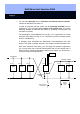
3. Use
activation units with antenna extender. Shorten the color-coded cable
on the antenna extender to the required length, pull the cable through the bore
hole in the aluminum screening sleeve and connect the cable to soldering
connections 16 to 20 as follows:
16 - green, 17 - blue, 18 - screening, 19 - red, 20 - yellow.
4.
Insert jumper B2! The range of the antennas is reduced if you use the
aluminum sleeve correctly.
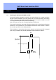
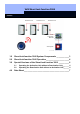
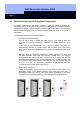
Bore a blind hole (
∅ 23 mm) in the outside wall, insert the antenna extender in
the blind hole and fix in position. (See drawing below). While doing this, make
sure that you get within at least 2 cm (approximately 3/4 inch) of the front side
of the antenna extender from the outside and that you guarantee a minimum
distance of at least 12 cm (4 3/4 inches) to the front side of the antenna
extender from the inside. This is approximately the thickness of the wall.
The distance between the antenna and activation unit must be at least 30 cm
(12 inches) and the distance from the locking cylinder to the antenna must be
at least 1 m (40 inches).
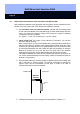
5. We recommend that you mark the position of the blind hole on the outside wall
with a red point or similar marking. The person authorized to activate the
system must hold the transponder at this point in order to be able to
communicate with the antenna extender.
6. Install the deactivation unit according to the description in Chapter 4.1.
Outside wall Inside wall
Antenna
extender
Activation
unit