
Unit installation

LON – Network 3065
Page 9
4.0 Lock Node
4.1 Method of Operation
4.2 Assembly Instructions
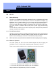
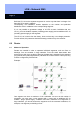
The LockNodes are pre-configured by SimonsVoss and are provided with numbers
(see the picture on page N6). These numbers (GID: GroupID, M: MemberID) are
entered in the set-up diagram for the building that is to be networked. During
installation, assign the LockNodes in the software on the basis of this set-up diagram.
Do not exchange the LockNodes, since otherwise no network connection can be
made to the digital components.
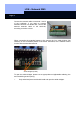
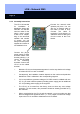
The LockNodes can be built into the lighting strip next to the door in a commercially
available flush-socket device or cavity socket (at least 40 mm deep) with
accompanying dummy cap. You should completely remove the network cable
screening in the flush socket device or cavity socket (only star-shaped wiring).
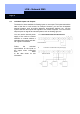
In networks with no topological structure and for BUS wiring, the screening of the
respective network cables should be connected in such a way (external terminal or
soldering, each with shrink sleeve) that screening is guaranteed for the entire network
cable.
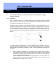
The terminator is then inserted at the last LockNode in the BUS wiring, and its
grounding cable (green-yellow) is connected to the screening (shield) or equipotential
bonding.
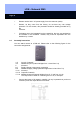
Wiring to the ceiling
Wiring to the floor
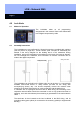
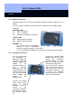
The LockNode takes on all programming
assignments in the network. Data is also transmitted
to the digital components by radio.