
Unit installation

LON – Network 3065
Page 15
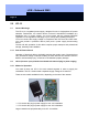
5.3 LPI-10 Compact (Version: compact construction with 230V power supply
from the customer)
5.3.1 Installation
Only a qualified expert who is familiar with and who complies with the generally
applicable rules of the technology and the regulations and standards valid at the time
is permitted to assemble and wire the LPI-10.
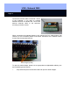
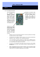
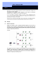
The device can be snapped on to DIN EN 50022-35 x 15 and DIN 50022-35 x 7.5
standard mounting rails. To snap the device in, hang it in with the catch ① in the top-
hat rail③ and press until the spring ② snaps into place (see following drawing). If it is
too hard to snap it in, loosen the spring ② somewhat. To remove it from the DIN rail,
use a screwdriver to loosen the spring ② in the direction of the arrow and remove the
device.
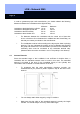
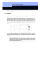
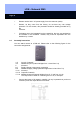
To ensure proper heat dissipation, you must install the device vertically, so that the
input and output terminals are at the top. There should be at least 5 cm (2 inches) of
clearance above and below the device in order to prevent interference with the air
circulation.
a Before beginning installation or maintenance work, switch off the system's
main switch and ensure that the system cannot be switched on again. During
maintenance work, provide a suitable disconnection device to disconnect the
unit from the electrical supply circuit.
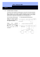
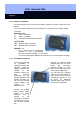
Use a screwdriver with a blade 3 mm (approximately 0.12 inches) wide. You
do not need any wire end ferrules for the terminals. You can use lines up to
thickness of 1 x 2.5 mm
2
or 2 x 1.5 mm
2
.