
Unit installation

LON – Network 3065
Page 16
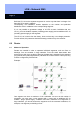
5.3.2 Method of Operation
You need at least one LPI-10 for each network segment in order to supply the Lock-
Nodes.
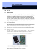
The LPI-10 (new construction) has 3 terminals for connection to the supply voltage:
Terminals:
INPUT AC 230V:
L1: 230V~ connection
N: 230V~ connection
PE: Potential compensation connection
OUTPUT BUS:
NET+: Network cable connection
NET-: Network cable connection
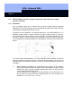
BRIDGE 1 + 2:
- For a network with no topological
structure or with a star-shaped
structure, bridge the "Bridge 1-2" connection
- You are not permitted to bridge this connection if you are using a bus topology.
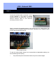
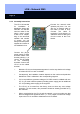
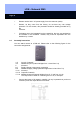
5.3.3 Assembly Instructions
The LPI-10 is intended
for installation in
distribution boxes with
DIN rails. Clamp the
voltage supplied from
outside to the
terminals marked for
that purpose.
Depending on the
structural situation and
number of groups, you
can also put several
power supplies and
routers in one
distribution box.
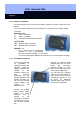
Connect the network cable
(twisted pair) here. For BUS
wiring, the connection
between "Bridge 1-2" stays
open, but for other wiring you
must insert a bridge here.
You can also lay a network
cable to the router (if there is
one). Connect the cable to
connecting terminals 17 and
18 there. An additional
network cable goes from the
router to the LockNodes.
Connect the outside
230V~ plug-in power
supply to these
terminals. This is
printed on the
connecting terminals.
Ground the LPI-10 on
the terminal labeled
PE.