
Unit installation

LON – Network 3065
Page 21
9.0 Network Cable
9.1 General Information
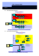
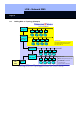
Every LockNode is networked with one line consisting of two twisted wires (twisted
pair). The data and the supply voltage are both transmitted over this line (see Fig. on
page N2 or N3). An LPI-10 or LPI-10 Compact module feeds the twisted pair line with
voltage (approximately 48 V DC).
9.2 Cable Laying
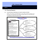
There are almost no restrictions placed on the cable laying when the given cable
types are used. As a matter of principle, however, placement parallel to cables with
strongly pulsating high voltage should be avoided. If, however, due to structural
reasons, it is possible to use only cable that has already been laid but which either
does not meet the required demands or which meets them only partially, the result
can be interference due to radiation from other cables or systems. This interference
can affect the performance capability of the network or can even lead to a complete
network blackout. Therefore, it is important in these cases to pay special attention to
cables or external systems that are in the vicinity of the transmission cable. This
means high power machine systems, elevators, microwave systems, or transmission
systems, for example.
Connect the shields of all network cables to one another. Normally, these are
connected to the potential compensation on the LPI-10.
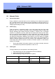
9.3 Cable Types
The type cable that you use depends on the following factors:
1. Total cable length (from the CentralNode to the last LockNode)
2. Cable length between the LockNodes
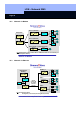
3. Network topology: wiring plan (star or bus system)
With no topology With no topology Bus topology with
terminators
Total length Distance between
nodes
Total length
JY (ST) Y 2x2x0.8
500 m 320 m 900 m
Category 5 450 m 250 m 900 m