SP1 Fire Indicator Panel Panel 4100ES-S1 Fire Indicator Operator’sManual Manual Panel Operator’s Operator’s Manual LT0395 Iss 1.
4100ES-S1 Fire Indicator Panel Operator’s Guide Fire detectors in the building are grouped into zones (searchable areas). Zones can be Isolated by pressing the zone’s isolate pushbutton on the panel – this prevents an alarm from activating the panel outputs. When a non-isolated detector detects an alarm, the fire panel rings the bell, calls the fire brigade, activates the Warning or Evacuation System (EWS) and any other programmed functions.
Manufacturer’s Details Approvals Australian Standard AS 4428.1, Control and Indicating Equipment. ActivFire Listing No. afp1682 Manufacturer The 4100ES-S1 is manufactured for : Tyco Fire Protection Products 47 Gilby Road Notting Hill VIC 3168 AUSTRALIA Phone : (03) 9538-7220 Fax : (03) 9538-7255 Copyright and Trademark Information 2012 Tyco Australia Pty Limited. All Rights Reserved.
Product/Site 4100ES-S1 Panel Supplied by: Installation Location Contract/Job Number As installed, FIP System Drawing Number Panel Installation Date Panel Commissioned Date Weekly Battery Test Day & Time Maintenance Company Telephone Service Contract Cautions & Warnings Some of the operation of the 4100ES-S1, as described in this manual, is dependent on custom configuration as performed by the field engineer.
Table of Contents Approvals .................................................................................................................... iv Manufacturer ............................................................................................................... iv Copyright and Trademark Information ........................................................................ iv Document ...................................................................................................................
Chapter 4 Testing and Controlling Points .....................................4-1 Introduction ...............................................................................................................4-1 In this Chapter ..........................................................................................................4-1 Alarm and Fault Test for Zones ............................................................................. 4-2 Alarm Test ....................................................
Chapter 9 Service-Related Operations ..........................................9-1 Introduction ...............................................................................................................9-1 In this Chapter ..........................................................................................................9-1 Setting Time and Date ............................................................................................ 9-2 Procedure ..............................................
Chapter 11 Printing Reports .........................................................11-1 Introduction .............................................................................................................11-1 In this Chapter ........................................................................................................11-1 Setting Printer Options ........................................................................................ 11-2 Available Options ..................................
x
Chapter 1 Overview Introduction This chapter provides an overview of the 4100ES-S1 operator interface and describes the normal appearance of the operator interface. In this Chapter Refer to the page number listed in this table for information on a specific topic.
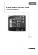
Typical Panel Layout Overview The 4100ES-S1 is supplied with an operator interface plus one expansion bay in a 21U sized cabinet. See Figure 1-1. The Zone Isolate modules are fitted into the expansion bays from left to right. The first zone is at the top of the leftmost module. Operator Interface SYSTEM IS NORMAL 08:23:43 am MON 11 -DEC-00 Alphanumeric display, Keypad, Acknowledge & Control Keys.
Basic System Description Overview The Simplex 4100ES-S1 Fire Indicator Panel (FIP) has three general functions. It monitors fire alarm initiating points (smoke detectors, heat detectors, etc.). It activates fire alarm notification devices (bells, strobes, brigade call) when an initiating point activates. It monitors and controls ancillary building equipment (fan controls, relays, etc.). Note: The term point is used extensively throughout this manual.
Basic System Description, Continued Overview, (continued) Table 1-1. Components of the Operator Interface (continued) LED/Key Description Refer To SYSTEM WARNINGS The System Warning LEDs – Isolation and Fault – indicate when abnormal, non-fire conditions occur. Chapter 3 Isolate LED and Ack Key When any zone is isolated, this LED turns on and the buzzer sounds until Isolate Ack is pressed.
Basic System Description, Continued Overview, (continued) Table 1-1. Components of the Operator Interface (continued) LED/Key Description Alphanumeric Display Displays text describing abnormal conditions for devices attached to the panel (e.g., smoke detector in main lobby is in alarm). Also displays system prompts and messages. Refer To Important Note: The degree to which you are allowed to control the system depends on the passcode assigned to you. See Chapter 7 for details on this.
Control Keys & Indicators Overview Control Keys & Indicator Functions The control keys and indicator LEDs are located on the far left of the operator interface as shown in Figure 1-3. Each control key is pressed to perform the labelled function, and the associated LED turns on to show the function is active. Pressing the key again de-selects the function and turns off the LED. Zone Alarm - The red indicator is on when there is an active (non-isolated) alarm in any zone.
Normal Appearance of Operator Interface Description The 4100ES-S1 operator interface panel shows the following under normal conditions: Green AC Power LED is ON – indicating the panel is receiving AC Power. All other LEDs off. Alphanumeric display reports that the system is normal and shows the current time and date, as shown below.
Chapter 2 Managing Alarm Conditions Introduction An alarm condition occurs when an actuating device (such as a manual call point, smoke detector, etc.) activates. The 4100ES-S1 indicates the presence of the alarm condition through messages it displays on the alphanumeric display, by illuminating the ALARM indicator LEDs, and by activating the building’s EWS and external bell. This chapter describes using the operator interface keys to investigate and manage alarm conditions.
Acknowledging Alarms What the System Does When an Alarm Occurs When the first alarm condition is detected by the 4100ES-S1, the panel does the following to indicate the presence of the alarm: Red Fire Alarm and common Zone Alarm LED indicators flash. Red Zone Alarm LED flashes on the display module showing the affected zone. Sounder (buzzer) pulses. Emergency Warning System (EWS) and External bell activate.
Acknowledging Alarms, Continued Procedure Use the following procedure to acknowledge alarm(s): 1. Unlock and open the enclosure door. Read the alphanumeric display. It alternates between the display shown in Figure 2-1 & the summary shown below. ***ALARM*** ALARMS = 1 2. Press to review. ISOLATED = 0 FAULT = 0 Press the key. Pressing the ACK key causes the following to occur: Buzzer silences Fire Alarm indicator changes from flashing to steady ON.
Isolating (Silencing) the Warning System or External Bell Overview When an alarm condition occurs, the building’s warning system activates to warn the building’s occupants about the alarm condition. In addition, the external bell sounds to indicate the location of the 4100ES-S1 to the fire brigade. During maintenance or testing, these outputs can be prevented from activating by isolating them before an alarm occurs.
Isolating ACF Outputs Overview The Ancillary Control Facility (ACF) consists of relay outputs which can be used to control equipment which is not part of the 4100ES-S1 fire alarm system, such as shutting down air conditioning or returning lifts to a certain floor. During maintenance or testing, these outputs can be isolated, to prevent unwanted annoyance to the building occupants. Operation Press the ACF ISOLATE key once.
Resetting Air Conditioning Control Overview The Ancillary Control Facility (see previous section) is used to control building air conditioning systems during a fire alarm. During the management of the alarm, it is often desirable to be able to delay restoring the air conditioning system to normal operation, e.g., to clear smoke even after the alarm conditions have been cleared. The A/C RESET control allows this delayed restoration.
Displaying Event Time Procedure 1. Select the point by repeatedly pressing the key (for a point in alarm), (for a point in fault), or (for an isolated point) until the desired point is displayed. 2. Press the key. The time and date that the point entered that state will be displayed.
Resetting Points Overview The Alarm state and some Fault conditions latch within the panel so they can be acknowledged and viewed. When the latched states are no longer required they can be reset. The condition that caused each point to go into alarm must be cleared before the system can reset to the normal state, (e.g. smoke cleared from smoke detectors, glass replaced in manual call point). Reset Procedure Press the key.
Chapter 3 Managing Fault and Isolate Conditions Introduction Fault conditions are used to indicate something wrong, e.g. the presence of a field wiring problem (circuit break, short or ground), somewhere between the 4100ES-S1 and one of its points. Faults are also used to indicate a problem with the option cards, power supplies, network card, etc., in the 4100ES-S1. Note that disabling a point introduces a fault condition into the system.
Acknowledging Fault or Isolate Conditions How the 4100ES-S1 Indicates the Presence of a Fault When a fault or isolate condition is detected by the 4100ES-S1, the operator interface does the following: The yellow ―FAULT‖ or ―ISOLATE‖ indicators flash The sounder (buzzer) sounds steady The alphanumeric display on the interface panel indicates the fault or isolate condition, as shown below. Figure 3-1.
Acknowledging Fault or Isolate Conditions, Continued Panel Operating Procedure – Fault Condition 1. Unlock and open the panel door. The yellow Fault indicator (LED) will be flashing and the sounder (buzzer) sounding. The alphanumeric display shows a message similar to the following. (This example shows a fault. The screen for isolate conditions is similar). **FAULT** ALARMS = 0 2. Press FAULT ACK to review. FAULTS = 1 ISOLATES = 0 Press the key.
Viewing Fault or Isolate Conditions Overview You can view the list of acknowledged fault or isolate conditions at any time by using the following procedure. 1. Press the or key to enter the fault or isolate list. The first fault or isolate condition in the list appears in the display. The top line indicates the custom label of the point. The bottom line contains two parts. The left side of the bottom line shows the type of device.
Chapter 4 Testing and Controlling Points Introduction This chapter describes using the panel’s action keys (ALARM TEST, On, Off, etc.) to test and control system zones and points. In this Chapter Refer to the page number listed in this table for information on a specific topic.
Alarm and Fault Test for Zones Alarm Test Alarm Test forces a zone into the alarm state. Once the zone is in alarm, you can check to see if the system reacts in the way that it has been programmed (i.e., do signals sound in the correct manner? do relays function correctly? etc.). Note: When you force a zone into alarm if the zone is not isolated then any outputs that are programmed to activate on alarm will activate, including Brigade signalling. Follow these steps to perform an alarm test on a zone. 1.
Isolating and De-isolating Zones Overview This section describes isolating and de-isolating zones. Isolating a zone does not prevent any of the points within the zone from going into the alarm state, but does prevent the activation of any outputs that are programmed to operate when the zone is in alarm. Pressing the key on a Zone Isolate module toggles the corresponding zone’s Isolate status. I.e., if the state of the zone is de-isolated, pressing the key isolates the zone.
Disabling and Enabling Points Overview Situations such as a malfunctioning detector causing false alarms, or an activated detector that prevents the system from being reset, can be temporarily overcome by disabling that particular point. Disabling a point allows the system to be reset while repairs are being made. It takes the point ―offline‖. Disabling a point prevents the point from entering an alarm condition for the duration of time it is disabled.
Turning a Point ON or OFF Overview It may be necessary during maintenance of the system to turn the outputs (for example notification devices and relays) on or off. Turning an output point off is effectively isolating that output. Once turned off, the output will not turn on, even if an alarm condition that is programmed to turn it on, occurs. After the maintenance it is necessary to return the output to automatic control.
Chapter 5 Selecting Points for Status or Control Introduction In this Chapter Many of the operations that can be accomplished from the operator interface first require you to select the point on which you want to perform the operation. Points can be selected in one of three ways. Alarm, Fault, or Isolate List.
Selecting Points from the Menu Overview Every system point is part of the ―Select a List of Points‖ list in the main menu. All points can be displayed sequentially by address order using this list option. To facilitate a search for a particular point, lists may be selected by point category (monitors, signals, auxiliary, input/output, pseudo points, etc.). A list of points may be selected, then scrolled through by using the and keys.
Selecting Points with the Function/Numeric Keypad Overview The Function/Numeric Keypad, shown in Figure 5-1 below, allows you to quickly select points. For example, pressing the ZONE key (key also labelled 1) selects the monitor zone category. After selecting a category, messages on the display prompt you for the specific point in the category.
Selecting Points with the Function/Numeric Keypad, Continued Selecting Points, (continued) Table 5-1. Function/Numeric Keypad Press this Key on Keypad Data to Enter ZONE – allows you to select a Monitor Zone point. followed by , where ZONE represents a zone card and is a number from x to y. After selecting a zone, use and to scroll through the points. SIG – allows you to select a Signal point.
Chapter 6 Displaying and Modifying Detailed Point Attributes Introduction This chapter describes displaying and modifying the attributes of a point. In this Chapter Refer to the page number listed in this table for information on a specific topic.
Display-Only Attributes Select a Point Points can be selected in one of three ways: through the alarm, fault, or isolate list, using the MENU keys, or with the Function/Numeric keypad. Refer to Chapter 5 for information on selecting a point. See the Attributes 1. Press the key. When you do this, the alphanumeric display shows the first attribute in the list.
Display-Only Attributes, Continued Summary of DisplayOnly Attributes, (continued) Category Table 6-1. More Info Display-Only Attributes (continued) Attribute Present sensitivity selected Average value TrueAlarm Sensors Only (smoke, heat, VESDA or 4-20mA) Alarm value Current value (per cent of alarm) Peak value (per cent of Alarm) Description Displays the current sensitivity of the device. Displays the average value recorded by the sensor. Displays the value required to trigger an alarm.
Modifiable Point Attributes Overview This section describes using the key to modify the attributes of a point. Select a Point Points can be selected in one of three ways — through the alarm, fault, or isolate list, using the MENU keys, or with the Function/Numeric keypad. Refer to Chapter 5 for information on selecting a point. See the Attributes 1. Press the key. When you do this, the alphanumeric display shows the first attribute in the list.
Modifiable Point Attributes, Continued Summary of Modifiable Attributes, (continued) Table 6-2. More Info Modifiable Attributes (continued) Attribute TrueAlarm Peak Analog Values Sensitivity (Alarm Threshold) Description Allows you to clear the peak value of a TrueAlarm sensor. Allows alarm. 6-5 you to set the value at which the device goes into The value can be any of the following.
Chapter 7 Setting Access Levels and Logging In Introduction This chapter describes setting the time and date on the system, logging in and out, and setting access levels for use by system operators. In this Chapter Refer to the page number listed in this table for information on a specific topic.
Operator Access Levels Overview Operator access levels 1 through 4 are available to support the system. Level 1 is the lowest operator access level and does not require a passcode to be entered to access functions identified at this level. Level 2 through 4 require a passcode of the required level or higher to be entered prior to performing the passcode protected functions. Controlling actions may be classified with access levels 2 through 4.
Logging In and Out of the System Introduction The 4100ES-S1 uses four access levels, referred to by the numbers 1 through 4, to control what operators can do with the system. The system typically operates at access level 1, which allows an operator to accomplish basic tasks without logging in to the system. Other functions, for example certain control functions, may be passcode protected to prevent access by unauthorized personnel.
Logging In and Out of the System, Continued Log In Procedure, (continued) If the passcode entered in Step 5 is correct, the following message is shown. a Passcode followed by ACCESS GRANTED After a brief pause, the system displays the granted access level, such as the level 2 message shown below. 1 = Login 2 = Logout CURRENT ACCESS LEVEL = 2 Press the key twice to exit out of the menu selections.
Logging In and Out of the System, Continued Log Out Procedure, (continued) 3. Press the <2> key. After a brief pause, the display shows a message similar to the one below. 1 = Login 2 = Logout CURRENT ACCESS REDUCED TO LEVEL 1 4. Press the key twice to exit. The display shows the system status.
Chapter 8 Viewing and Clearing Historical Logs Introduction When an abnormal condition occurs, a record of the event is placed in one of two logs generated by the system, depending on the nature of the condition. These logs are: Historical Alarm Log Historical Fault Log The historical logs contain a time stamp of the events surrounding abnormal conditions in the system. The information displayed with these lists are historical data only and will not contain any current point status.
Viewing and Clearing the Historical Alarm and Fault Logs Viewing Logs The Historical Alarm and Fault Logs can be viewed from the 4100ES-S1 operator interface. 1. Press the
Chapter 9 Service-Related Operations Introduction This chapter describes service-related status and control procedures. In this Chapter Refer to the page number listed in this table for information on a specific topic.
Setting Time and Date Procedure Follow these steps to set the time and date on the panel. 1. Press the
Displaying Software Revision Overview Follow these steps to display software revision information. 1. Press the MENU key. 2. Press the or keys until the prompt reads, ―Display Software Revision Level?‖ 3. Press . A display similar to the following appears. SYS REV: 11.02.08 CFIG FORMAT: 112 JOB: JOB1 REV:6 13-OCT-00 4. Interpret this information as follows. SYS REV: Specifies the revision of the executive software (operating system of the FIP) loaded in the panel.
Viewing Card Status Information Overview Every card, including the Master Controller and all option cards, has a series of Card Status Points associated with it. For the SPS (System Power Supply) these points include System Voltage, System Current, Battery Voltage, etc. Procedure Power Supply/Charger Voltage and Current Readings 1. Press the MENU key. 2. Press the or keys until the prompt reads, ―Display Card Status?‖ 3. Press .
Displaying Network Node Information Overview Network systems consist of multiple panels linked via a 4120 network. Each panel includes a programmer-defined node number, used to identify the panel on the network. The following section describes how to determine a panel’s node number. The node number is required when selecting a network point. See ―Selecting Points‖ in Chapter 5 for more information on doing this. Procedure 1. Press the MENU key. 2.
Lamp Test Procedure The ―LAMP TEST‖ push-button on the operator interface is used to determine local lamp (LED) failures within the system. LEDs on the 4100ES-S1 operator interface and Switch/LED Display Modules illuminate. All segments on the LCD also change to squares. Perform the following procedure to determine LED or LCD failures. 1. Press the ―LAMP TEST‖ push-button. All LEDs should illuminate (LEDs should stay illuminated as long as the push-button is depressed).
Displaying IDNet & Mapnet Device Status Introduction The IDNet options allow the use of addressable devices and TrueAlarm sensors with the 4100ES-S1 FIP. Addressable devices communicate the exact location of an alarm to the system operator interface panel, improving recognition of the condition and subsequent response. It also pinpoints the precise location of fault conditions via the device custom label. Throughout this section, operations described for IDNet are also applicable for Mapnet.
Displaying IDNet & Mapnet Device Status, Continued TrueAlarm Sensor Display Values, (continued) Press the key to obtain the next display: Device Address: 3-1 IDNet Device: M1-1 Press the key to obtain the next display: 1-Force on card LED IDNet CARD Type: IDNet Pressing key <1> will turn on the LED indicator on the IDNet Card in the FIP control rack and pressing it again will turn the LED off. Press the key to move onto the next display.
Displaying IDNet & Mapnet Device Status, Continued TrueAlarm Sensor Display Values, (continued) To view the average value of samples received from the sensor press the key again. Level 3 – Room 74 Average Value = 75 / Alarm level = 135 This is the present average of the last 2048 samples received from the sensor. The Alarm Level is the binary value that is used to determine alarm conditions. This value will change over time as the panel compensates for environmental conditions.
Chapter 10 System Test Procedures Introduction The following test features can be used when commissioning after the system is installed, and during periodic testing as required by code. Refer to Chapter 12, Maintenance Procedures for detail on these. In this Chapter Refer to the page number listed in this table for information on a specific topic.
Walk Test™ Overview Walk Test™ is a software-based function and is programmed to meet the customer requirements. The system will pulse the signals for alarm conditions, then reset. The signals will sound steady for 4 seconds to indicate fault conditions, then reset. A silent Walk Test™ may be performed (no signals will sound) and logging of events may be selected.
Walk Test™, Continued Zone Coding Option, (continued) = Zone 3 (three long pulses) = Zone 12 (one long, pause, two long pulses) = Zone 20 (two long and two short pulses) = Zone 102 (one long, two short, and two long pulses) NOTE: Zero Code = 2 short pulses. Zone coding may be disabled for each of the eight Walk Test™ groups, Group 0 through Group 7, using the interface panel’s display. When zone coding is disabled ( key to ZERO), a ―0‖ code is always used, even for the first alarm.
Walk Test™, Continued Enabling Walk Test, (continued) <3> Key - Allows you to choose between Zone Coding and Zero Coding. In Zone Coding a PNIS code for the tested zone is played (e.g., Zone 12 is code 1-2). In Zero Coding, two quick pulses (code 0) are heard. In both cases, when a fault is reported from a zone, the signal circuits turn ON for 4 seconds. <4> Key - Enables/disables silent Walk Test™.
Walk Test™ Features Introduction The Walk Test™ function has the following features: Abort Audible and Delay on Reactivation Active/Not Active Auto Abort on Alarm Auto Abort on Time-out Control Lists Delay Before Reset Log/No Log (Logging Option) Monitor Zone List Programmer Configuration Sig/No Sig (Silent Walk Test™ Selection) System Fault Fault Audible Zone Code/Zero Code. These features are discussed in the following paragraphs.
Walk Test™ Features, Continued Delay Before Reset The programmer has the ability to set a Reset Time Delay. The delay time period starts after a zone alarm is detected and runs until the detector is reset. The length of the delay may be from 15 to 60 seconds, and may be adjusted depending on the method used to simulate an alarm. A longer value is desired if smoke is used to bring in each detector. By default, the delay is set to 15 seconds.
Walk Test™ Features, Continued Fault Audible When a zone fault is detected, the Walk Test™ signals sound continuously for four seconds. Zone Code/Zero Code The <3> key is used to enable/disable Zone Coding. By default, Zone Coding is enabled.
Walk Test™Procedures How to Enter Walk Test Mode Once the passcode has been entered, you may enter the Walk Test™ mode by performing the following procedures. 1. Press the
Walk Test™Procedures, Continued How to Enter Walk Test Mode, (continued) 5. Press the <1> key to enable/disable the Walk Test™ mode. The SYSTEM FAULT LED illuminates, the tone-alert sounds, and the LCD displays the following message. 1 = ON>off 2 = no>LOG WALK TEST GROUP 0 3 = ?>ZONE 4 = NO key to scroll to the next Walk Test™ group. Then press the <1> key to enable that group.
Walk Test™Procedures, Continued How to Turn a Point Off The key press will turn a control point off and prevent the automatic override, thus causing it to remain OFF. This action will result in a system fault. The normal state of all control points is AUTO. The key press has no effect on monitor points. The point to be turned OFF must first be identified to the system.
Walk Test™Procedures, Continued How to Turn a Point On, (continued) To turn a point ON, perform the following procedures. 1. Ensure the point to be turned ON is shown on the alphanumeric display. A typical point (SIG2) is shown below. MASTER SIGNAL POINT 2, SIG2 SIGNAL CIRCUIT 2. OFF Press the key. A typical display is shown below. Press to force ON SIGNAL CIRCUIT: SIG2 3. Press the key. A typical display is shown below. MASTER SIGNAL POINT 2, SIG2 SIGNAL CIRCUIT 4.
Walk Test™Procedures, Continued How to Return a Point to Auto, (continued) 2. Press the key. A typical display is shown below. Press for AUTOmatic control SIGNAL CIRCUIT: SIG2 3. Press the key. A typical display is shown below. MASTER SIGNAL POINT 2, SIG2 SIGNAL CIRCUIT 4. OFF Press the key. The display shows the following message.
Walk Test™Procedures, Continued How to Enable a Disabled Point, (continued) 3. Press the key. The alphanumeric display shows the following message. Please stand by . . . ZONE 12 will ENABLE in 60 seconds WARNING If the zone is still in alarm, a WARNING is displayed which tells you that the system will sound an alarm if the timer (60 seconds) times out. TO ABORT THE ENABLE, PRESS THE KEY. If an alarm condition exists, the following is shown on the alphanumeric display.
Chapter 11 Printing Reports Introduction This chapter describes printer options and how to print a report. In this Chapter Refer to the page number listed in this table for information on a specific topic.
Setting Printer Options Available Options The 4100ES-S1 includes two printer options: Select Report Printer and Terminate Current Report. Follow these steps to set these options. 1. Press the
Printing a Report Overview Procedure The system can generate any of the following reports. Report Description Alarm History Log Report Report includes all information contained in the alarm history log – device custom label, time and date device entered alarm. Fault History Log Report Report includes all information contained in the fault history log – device custom label, type of trouble, time and date device experienced trouble.
Chapter 12 Maintenance Procedures Introduction It is a requirement of AS 1851 - Maintenance of Fire Protection Systems and Equipment, that tests be carried out to ensure the system is fully functional. Usually a maintenance company, under a Service Agreement, carries out the tests. In this Chapter Refer to the page number listed in this table for information on a specific topic.
Monthly Tests Monthly Tests AS 1851 Description Item No. 2.1 Fire Alarm 2.2 2.4 Fault Isolate Action Required and Pass/Fail Criteria Simulate an alarm condition via an alarm zone and confirm that all required visual and audible indications and output controls activate. Where the CIE is monitored, ensure the alarm is processed by the monitoring service provider. Where the alarm is not automatically acknowledged, an alternative method of confirmation is required.
Annual Tests Additional Tests to be Done Annually. AS 1851 Description Action Required and Pass/Fail Criteria Item No. 2.13 Visual Test the operation of CIE LED and alphanumeric Indicators indicators. 2.14 Warning Test the operation of the warning system. System 2.
Battery Load Discharge Testing (AS 1851 Item 2.15) The 4100ES-S1 Fire Alarm Panel has no provision for load discharge testing of the battery at the levels required for yearly testing to AS 1851-2005. PSU Supervision (AS 1851 Item 2.3) 4100ES-S1 does not include built-in facilities to carry out this test. A suitably rated bench power supply connected to the battery terminals with main power turned off may be used instead.