
Operator`s manual


1-2
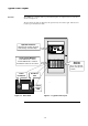
The 4100ES-S1 is supplied with an operator interface plus one expansion bay in a 21U sized
cabinet. See Figure 1-1.
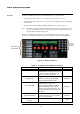
The Zone Isolate modules are fitted into the expansion bays from left to right. The first zone
is at the top of the leftmost module.
Typical Panel Layout
Overview
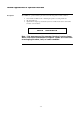
Figure 1-1. Zone detail
Emergency Operating Instructions
SYSTEM IS NORMAL
08:23:43 am
MON 11
-
DEC
-
00
Fire Control
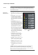
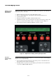
Figure 1-1. Typical Panel Layout
Operator Interface
Alphanumeric display, Keypad,
Acknowledge & Control Keys.
Zone Isolate Modules
Red LED indicates alarm,
Yellow LED indicates isolation,
Pushbutton isolates & de-isolates
Ancillary
Controls
These are optional,
panel (site) specific
controls
Isolate
Pushbutton
Red Alarm
LED
Yellow
Isolate
LED