
Specifications


5-17
SPS Auxiliary Power Wiring, Continued
{xe "auxiliary power: isolators and"}{xe "IDNet power isolator"}{xe "isolators"}{xe
"power isolators"}
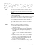
The SPS can connect to auxiliary power appliances via the dedicated auxiliary power tap
(TB3). See Figure 5-9. If more power is needed, any of the three NAC outputs can be
used for auxiliary power.
B+
0V 24V
AUX POWER
B- A+ A- B+ B- A+A- B+B- A+A-
AUXILIARY
POWER
AUXILIARY
POWER
AUXILIARY
POWER
AUXILIARY
POWER
Figure 5-9. Auxiliary Power Wiring
Wiring
Maximum load per NAC: 3A alarm, 2A non-alarm load
Maximum load per Fuse Distribution Board output: 1A, limited to 2A collectively.
Class A wiring is possible only if 4090-9117 Power Isolators are used.
Ferrite beads must be fitted on NAC wiring. Use kit 4100-5129 (3 beads).
Devices
Primary Return
TB1 TB2
24V
0V
TB1 TB2
To SPS
Class A Aux power wiring requires the use
of 4090-9117 IDNet Power Isolators, as
shown above.
4090-9117
ISOLATOR
4090-9117
ISOLATOR
SPS
TB2
TB3
Dedicated auxiliary
power screw terminal
(configured in the
Programmer)
NAC points must be
reconfigured as
auxiliary power
output points in the
programmer
0.75 m
2
to 4 mm
2
0.75 mm
2
to 4 mm
2
Ferrite bead
required for EMC
compliance. Use
SX0005 or kit
4100-5129.
Fuse Distribution Board