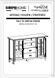
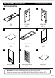
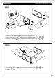
SIMP HOME I ® I L I F E B Y D E S I GN ARTISAN / HOLDEN / STRATFORD TALL TV MEDIA STAND MODEL # AXCART17-TB 1/22
SIMP HOME I I ® L I F E B Y D E S I GN Questions, problems, assembly help, missing parts? No need to return the product, we will gladly help and ship your replacement parts free of charge Please call Customer Service at 1-866-518-0120 ext. 262 Monday to Friday between 9 am – 4 pm EST or go to www.simpli-home.
IMPORTANT : Please read this manual carefully before beginning assembly of this product. Keep this manual for future reference. SAFETY INFORMATION CAUTION: Injuries and damage can occur from furniture tip over if product is not properly anchored to the wall. Use the Furniture Anti-Tipping Restraint provided with the product. Consult our assembly instructions for help.
IMPORTANT : Please read this manual carefully before beginning assembly of this product. Keep this manual for future reference. CARE and MAINTENANCE Perhaps the greatest environmental damage to wood furniture comes from wide swings in relative humidity (RH) in our homes. Wood absorbs and desorbs water as relative humidity rises and falls, and in doing so it swells and shrinks. Making matters worse, it expands and contracts unequally along different grain directions.
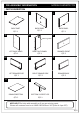
PRE-ASSEMBLY INFORMATION MODEL # AXCART17-TB PARTS DESCRIPTION A BL BR Fron t/A vant vant t/A Fron Fron t/A vant TOP QTY 1 C LEFT SIDE QTY 1 D RIGHT SIDE QTY 1 EL Fron t/A vant vant t/A Fron ER LEFT DIVIDER QTY 1 BOTTOM SHELF QTY 1 CENTRE SHELF QTY 1 G F Fron t/A vant RIGHT DIVIDER QTY 1 DOOR (L&R Same) QTY 2 SHELF PART QTY 4 NEED HELP? For help with assembly or if you are missing a part, Please call customer service at 1-866-518-0120 ext.
PRE-ASSEMBLY INFORMATION MODEL # AXCART17-TB PARTS DESCRIPTION H I BACK PANEL QTY 1 SHELF PART QTY 1 KL J BACK PANEL QTY 1 L KR Warning Label LEFT BACK PANEL QTY 1 ML RIGHT BACK PANEL QTY 1 N MR RIGHT DRAWER SIDE QTY 2 LEFT DRAWER SIDE QTY 2 O DRAWER FRONT QTY 2 DRAWER BACK QTY 2 P DRAWER BOTTOM QTY 2 BOTTOM SUPPORT LEG QTY 1 NEED HELP? For help with assembly or if you are missing a part, Please call customer service at 1-866-518-0120 ext.
PRE-ASSEMBLY INFORMATION MODEL # AXCART17-TB HARDWARE DESCRIPTION 1 2 ALLEN KEY SCREW M6 X 30 mm QTY 26 4 3 CAM LOCK PIN CAM LOCK QTY 20 SETS 5 7 6 PHILLIPS SCREW M3 X 15 mm QTY 8 PHILLIPS SCREW M3 X 12 mm QTY 12 8 HANDLE M4 X 30 mm QTY 4 SETS 10 ALLEN KEY QTY 1 PHILLIPS SCREW ROUND HEAD M4 X 15 mm QTY 25 9 MAGNET AND PLATE QTY 2 SETS SHELF SUPPORT QTY 30 11 a. M4 X 25 - QTY 2 ( 1 is extra ) b. M4 X 15 - QTY 1 c.
COMPONENTS – KEY DIAGRAM MODEL # AXCART17-TB A Fron t / Av ant KL I KR EL ER BR H G G C Fron t/A vant Fron t/A vant G G BL J F Fron t/A vant Fron t/A vant Front / Avan t D F P MR N ML O L 8/22
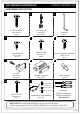
ASSEMBLY MODEL # AXCART17-TB STEP 1 B MR ML L 2 1. Attach 4 Cam Lock Pins 2 to back of Left Drawer Front L . 2. Align Cam Lock Pins with guide holes and attach Drawer Sides ML , MR . 3. Insert 2 Cam Locks 2 into guide holes on each Drawer Side ML , MR . 4. Use flathead screwdriver to secure Cam Locks. STEP 2 MR O ML L 1. Slide Drawer Bottom O firmly into slots on Drawer Sides ML , MR and Drawer Front L .
ASSEMBLY MODEL # AXCART17-TB STEP 3 B N O 1 3 1. Align Drawer Back N with Drawer Bottom O and press firmly into slot. 2. Attach back using 2 Allen Key Screws 1 through guide holes on each side. 3. Use Allen Key 3 to tighten screws. Do not over tighten. STEP 4 7 L 1. Use Phillips screwdriver to attach Handle 7 to Drawer Front L . Repeat Step 1-4 for the second drawer .
ASSEMBLY MODEL # AXCART17-TB Front / Avant STEP 5 ER Front / Avant C EL 2 1. Attach 3 Cam Lock Pins 2 to each Divider EL , ER . 2. Align Cam Lock Pins with guide holes and attach Center Shelf C . 3. Insert 6 Cam Locks 2 into guide holes on Center Shelf C . 4. Use flathead screwdriver to secure Cam Locks.
ASSEMBLY Front / Avant Front / Avant STEP 6 MODEL # AXCART17-TB ER Front / Avant EL D 1 3 1. Attach Dividers EL , ER to Bottom Shelf D using 6 Allen Key Screws 1 through guide holes.
ASSEMBLY MODEL # AXCART17-TB Front / Avant STEP 7 Front / Avant Front / Avant Front / Avant Front / Avant BR D Left Right BL 2 2 1. Attach 6 Cam Lock Pins 2 to 2 Sides BL , BR using pre-drilled holes. 2. Align Cam Lock Pins with guide holes on Bottom Shelf D and attach Bottom Shelf D . 3. Insert 6 Cam Lock 2 into guide holes on Bottom Shelf D . 4. Use a flathead screwdriver to tighten Cam Locks into Pins.
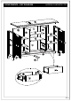
ASSEMBLY MODEL # AXCART17-TB Front / Avant Front / Avant STEP 8 Front / Avant Front / Avant ER EL Front / Avant BR BL P D 10 P 1. Attach Bottom Support Leg P to Bottom Shelf D using 4 Phillips Screws 10 . 2. Use Phillips screwdriver to tighten screws. Do not over-tighten.
ASSEMBLY MODEL # AXCART17-TB STEP 9 1 1 3 3 BR Front / Avant Front / Avant ER EL Front / Avant Front / Avant Front / Avant Front / Avant A BL 1. Attach Top A to 2 Sides BL , BR and 2 Dividers EL , ER using Allen Key Screws 1 through guide holes. 2. Use Allen Key 3 to tighten screws. Do not over-tighten.
ASSEMBLY MODEL # AXCART17-TB STEP 10 Note: The back of the tv frame does not have pre-drilled holes to a ach the back panels. KL I J KR Fron t/A vant Fron t / Av ant Fron t/A vant Fron t / Av ant Fron t / Av ant Fron t/A vant Warning Label 6 Fron t/A vant I Fron t / Av ant KL KR J 1. Use Phillips screws Round Head 6 to attach Back Panels I , J , KL , KR through guild holes. 2. Use Phillips screwdriver to tighten screws.
ASSEMBLY MODEL # AXCART17-TB STEP 11 Last Step ( after adjust the door ) First Step 4 4 4 F 8 5 BR BL D F 5 8 7 1. Attach hinges on Doors F to Sides BL , BR using Phillips Screws 4 into pre-drill holes: - Using Phillips screwdriver to attach Screws 4 at middle hole of hinges for both top & bottom hinges. - Adjust the door to ensure they are aligned straight & square with bottom shelf & side.
ASSEMBLY MODEL # AXCART17-TB STEP 12 A shelf level 1 shelf support anti - tipping shelf level 2 9 shelf level 3 9 G H G 1. Use 4 Shelf Supports 9 for each Shelf H or G in desired location . 2. 2 Shelf Supports 9 may be used on back top of each Shelf H or G as a tipping restraint.
ASSEMBLY MODEL # AXCART17-TB STEP 13 1. Insert assembled drawers into glides on assembled Tall TV Media Stand.
FURNITURE TIP OVER RESTRAINT ASSEMBLY WARNING Serious or fatal crushing injuries can occur from furniture tip-over. If the furniture tip over restraint kit is not in the box, please contact our customer service department in order to obtain another kit before using the furniture. B STEP 14 NOTE: The screwdriver is not included in the hardware pack.
FURNITURE TIP OVER RESTRAINT ASSEMBLY Furniture Tip Over Restraint Instructions: 1. Attach one of the mounting brackets securely to the back edge of the furniture. Use the shorter screw. 2. Determine where furniture is to be placed and mark location on the wall for mounting bracket screw hole approximately 2 inches below the bracket mounted to the furniture. x 3. 4. 5. 6. 7. Drill a 3/16 inch hole in the wall.
SIMP HOME I I ® L I F E B Y D E S I GN WARRANTY Thank you for purchasing a Simpli Home – Wyndenhall – Brooklyn + Max product. These products have been made to demanding, high-quality standards and are guaranteed for domestic use against manufacturing faults for a period of 12 months from the date of purchase. This warranty does not affect your statutory rights. In case of any malfunction of your product (failure, missing parts, etc.