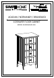
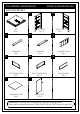
TM SIMP HOME ® LIFE BY DESIG N TM ACADIAN / NORMANDY / BRUNSWICK 4 DRAWER FLOOR CABINET MODEL # AXCBSACA02-WH 1/16
TM SIMP HOME ® LIFE BY DESIG N TM Questions, problems, assembly help, missing parts? No need to return the product, we will gladly help and ship your replacement parts free of charge Please call Customer Service at 1-866-518-0120 ext. 262 Monday to Friday between 9 am –4 pm EST or go to www.simpli-home.
IMPORTANT : Please read this manual carefully before beginning assembly of this product. Keep this manual for future reference. SAFETY INFORMATION CAUTION: Injuries and damage can occur from furniture tip over if product is not properly anchored to the wall. Use the Furniture Anti-Tipping Restraint provided with the product. Consult our assembly instructions for help.
IMPORTANT : Please read this manual carefully before beginning assembly of this product. Keep this manual for future reference. CARE and MAINTENANCE Perhaps the greatest environmental damage to wood furniture comes from wide swings in relative humidity (RH) in our homes. Wood absorbs and desorbs water as relative humidity rises and falls, and in doing so it swells and shrinks. Making matters worse, it expands and contracts unequally along different grain directions.
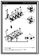
PRE-ASSEMBLY INFORMATION . PART DESCRIPTION A Fron t/A . . BL van t BR t Fron TOP QTY 1 . MODEL # AXCBSACA02-WH Fron ant / Av t/A LEFT SIDE QTY 1 . C . CROSS BAR QTY 2 E CROSS BAR QTY 3 . FL DRAWER FRONT QTY 4 . FR LEFT DRAWER SIDE QTY 4 . t RIGHT SIDE QTY 1 D . van G RIGHT DRAWER SIDE QTY 4 DRAWER BACK QTY 4 . H I DRAWER BOTTOM QTY 4 BACK PANEL QTY 1 NEED HELP? For help with assembly or if you are missing a part, Please call customer service at 1-866-518-0120 ext.
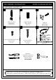
PRE-ASSEMBLY INFORMATION . MODEL # AXCBSACA02-WH HARDWARE DESCRIPTION 1 2 . CAM LOCK PIN CAM LOCK QTY 26 SETS . . 3 WOOD DOWEL Ø8 X 30mm QTY 16 . 4 . 5 PHILLIPS SCREW ROUND HEAD M4 X 15mm QTY 14 HANDLE M4x25mm QTY 4 SETS 6 PHILLIPS SCREW M4 X 40mm QTY 16 a.M4X25mm-QTY2 (1siextra) b.M4X15mm-QTY1 c.
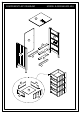
COMPONENTS-KEY DIAGRAM MODEL # AXCBSACA02-WH A Fron t/A van t BR I Fron t/A C van t D BL D C D G FR H FL E 7/16
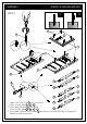
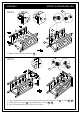
ASSEMBLY MODEL # AXCBSACA02-WH P STEP-1 X 1 1 A t/ Fron nt Ava 1 1 BL Fron Fron t/A t/A van t van t BR 2 2 2 C 2 2 C 2 2 D 2 2 D 2 2 D 2 1. Attach Cam Lock Pins 1 into pre-drilled holes on each part A , BL , BR . 2. Insert Wood Dowels 2 into guide 2 holes on each part BL , BR , C , D . 3. Use rubber mallet to tap Dowels 2 into bottom of holes securely. 1/2 length of Dowels should be exposed.
ASSEMBLY MODEL # AXCBSACA02-WH STEP-2 C D C D D C D BR Fron t/A van t D C D D BR C 1 1 1 1. Align Wood Dowels and Cam Lock Pins with guide holes and attach parts C , D to Right Side BR . 2. Insert one Cam Lock 1 into guide holes on each part D . 3. Use Phillips screwdriver to secure Cam Locks.
ASSEMBLY MODEL # AXCBSACA02-WH 1 STEP-3 D C 1 BL C C BL D D D D BR 1 BR D D 1. Repeat Step-2 for the Left Side BL . STEP-4 Front / Avant 1 BL A A BL Front / Avant BR BR 1. Align Dowels and Cam Lock Pins with guide holes and attach Top A to Sides BL , BR . 2. Insert two Cam Locks 1 into guide holes on Sides BL , BR . 3. Use Phillips screwdriver to secure Cam Locks.
ASSEMBLY MODEL # AXCBSACA02-WH STEP-5 4 Note: Thebackofthecabinetframedoesnothave pre-driledholestoattachthebackpanels. Fron Fron t/A t/A vant van t A A I I 1. Attach the Back Panel I to back frame using Phillips Screws Round Head 4 through guide holes from Back Panels. 2. Use Phillips Screwdriver to tighten screws. Do not over-tighten. P STEP-6 1 X 1 E E E E 1. Attach four Cam Lock Pins 1 into pre-drilled holes on each Drawer Front E . 2.
ASSEMBLY MODEL # AXCBSACA02-WH STEP-7 1 I 5 5 I FR FL H FR FR 1 FL H FL 1 E X4 E E X4 X4 5 3 E X4 X4 1.AlignCamLockPinswithguideholesandattachDrawerSides FL,FRtoDrawerFrontE. 2.InserttwoCamLocks1intoguideholesoneachDrawerSide FL,FR. 3.UsePhilpsscrewdrivertosecureCamLocks.Donotover-tighten. 4.SlideDrawerBottomHfirmlyintoslotsonDrawerSidesFL,FRandDrawerFrontE. 5.AlignDrawerBackIwithDrawerBottomHandpressfirmlyintoslot. 6.
ASSEMBLY MODEL # AXCBSACA02-WH STEP-8 1. Insert assembled drawers into glides on assembled cabinet.
FURNITURE TIP OVER RESTRAINT ASSEMBLY WARNING Serious or fatal crushing injuries can occur from furniture tip-over. If the furniture tip over restraint kit is not in the box, please contact our customer service department in order to obtain another kit before using the furniture. STEP-9 NOTE: The screwdriver is not included in the hardware pack.
FURNITURE TIP OVER RESTRAINT ASSEMBLY Furniture Tip Over Restraint Instructions: 1. Attach one of the mounting brackets securely to the back edge of the furniture. Use the shorter screw. x P 2. Determine where furniture is to be placed and mark location on the wall for mounting bracket screw hole approximately 2 inches below the bracket mounted to the furniture. x 3. 4. 5. 6. 7. P Drill a 3/16 inch hole in the wall.
TM SIMP HOME ® LIFE BY DESIG N TM WARRANTY Thank you for purchasing a Simpli Home – Wyndenhall – Brooklyn + Max product. These products have been made to demanding, high-quality standards and are guaranteed for domestic use against manufacturing faults for a period of 12 months from the date of purchase. This warranty does not affect your statutory rights. In case of any malfunction of your product (failure, missing parts, etc.) please contact us at our toll free service line at 1-866-518-0120 ext.