Ela / Cantina / Adora Console Table Model # AXCELA06-SMB TM TM 1
Great quality is a right. Thank you for shopping with Simpli Home, America's top brand for high-value furniture. It's time to register your product warranty. It's quick and easy. And you'll be happy you did. ü Activate your 1-year warranty ü Automatic entry to win a $500 gift certificate ü Earn instant rewards and save simpli-home.
Review your product and collect rewards! Thank you for your purchase! We hope you enjoy it. We’d love your feedback. Please share a review and get instant rewards! simpli-home.com/product-review Share photos and get your cash back! Send us images or share them on social and qualify for instant rewards. You may even receive store credit on your entire purchase! simpli-home.
For Fastest Customer Service: 1. Open your phone’s camera. 2. Point your phone’s camera at the QR code to scan. 3. Click on the pop up. 4. You’ll be taken to our customer service page. 5. Fill the form with your order information and issue. 6. Submit form. 7. A customer service associate will contact you. Other ways to contact us… Email Us Visit Us Call Us customerservice@simpli-home.com Visit our site directly at www.simpli-home.
IMPORTANT : Please read this manual carefully before beginning assembly of this product. Keep this manual for future reference. Safety Information CAUTION: Injuries and damage can occur from furniture tip over if product is not properly anchored to the wall. Use the Furniture Anti-Tipping Restraint provided with the product. Consult our assembly instructions for help.
Care & Maintenance This furniture is designed for indoor use. Perhaps the greatest environmental damage to wood furniture comes from wide swings in relative humidity (RH) in our homes. Wood absorbs and desorbs water as relative humidity rises and falls, and in doing so it swells and shrinks. Making matters worse, it expands and contracts unequally along different grain directions. As humidity changes, the components of wooden objects are continually pushing and pulling against each other.
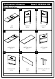
Pre-Assembly Information Model # AXCELA06-SMB Part Description . . A . BL BR Front Fro nt /A van / Ava Front nt / Ava nt t LEFT SIDE QTY 1 TOP QTY 1 . . C RIGHT SIDE QTY 1 . D EL Fro nt / Ava nt Front MIDDLE SHELF QTY 1 . ER . F Front LEFT DIVIDER QTY 1 BOTTOM SHELF QTY 1 .
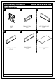
Pre-Assembly Information Model # AXCELA06-SMB Part Description . . H . I DOOR QTY 2 . JL . JR .
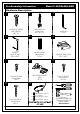
Pre-Assembly Information Model # AXCELA06-SMB Hardware Description . . 1 . 2 3 CAM LOCK PIN CAM LOCK QTY 24 SETS ALLEN KEY SCREW M6 X 30mm QTY 26 . . 4 ALLEN KEY QTY 1 . 5 6 HANDLE M4 X 15 mm QTY 4 SETS . WOOD DOWEL Ø8 X 30mm QTY 6 . 7 . 8 9 ADJUSTABLE HINGE Ø35 QTY 4 PHILLIPS SCREW M3 X 15mm QTY 8 . MAGNET AND PLATE QTY 2 SETS PHILLIPS SCREW M4 X 15mm QTY 24 . 10 11 a. PHILLIPS SCREW M4 X 30mm QTY 4 b. c.
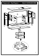
Components - Key Diagram Model # AXCELA06-SMB Fron t /Av ant A Fron t /Av ant F BR Fron t /Av ant BL H H Fron t /Av ant Fron t /Av ant ER EL Fron t /Av ant C D G K JR L JL I 10
Assembly Model # AXCELA06-SMB Step 1 P X 2 2 2 I 1. Attach four Cam Lock Pins 2 into pre-drilled holes on back of Drawer Front I . 2. Use Phillips screwdriver to secure Cam Lock Pins. Do not over-tighten. Step 2 JR JR JL JL I I 2 1. Align Cam Lock Pins with guide holes and attach Drawer Sides JL , JR to Drawer Front I . 2. Insert two Cam Locks 2 into guide holes on each Drawer Side JL , JR . 3. Use Phillips screwdriver to secure Cam Locks. Do not over-tighten.
Assembly Model # AXCELA06-SMB Step 3 L JR L JR JL JL I I 1. Slide Drawer Bottom L firmly into slots on Drawer Sides JL , JR and Drawer Front I . Step 4 3 1 1 K K JR L JR L 1 JL JL I I 2. Align Drawer Back K with Drawer Bottom L and press firmly into slot. 3. Attach Drawer Back using two Phillip Screws 1 through guide holes on each Drawer Side JL , JR . 4. Use Allen Key 3 to tighten Screws. Do not over-tighten.
Assembly Model # AXCELA06-SMB Step 5 4 I 1. Use Phillips screwdriver to attach Handle 4 to Drawer Front I . Repeat Step 1 - 5 for the second drawer.
Assembly Model # AXCELA06-SMB Step 6 P X 5 2 2 Fron t / Av ant BR 2 5 2 2 BL Fron t / Av ant 5 ER Fron t / Av ant Fron t / Av 5 1. 2. 3. 4. ant EL 5 Attach eight Cam Lock Pins 2 into pre-drilled holes on each Side BL , BR . Use Phillips screwdriver to secure Cam Lock Pins. Do not over-tighten. Insert Wood Dowels 5 into guide holes on Sides BL , BR and Dividers EL , ER . Use rubber mallet to tap Dowels 5 into bottom of holes securely. 1/3 length of Dowels should be exposed.
Assembly Model # AXCELA06-SMB Step 7 3 ER 1 Front / Avant Front / Avant EL Front / Avant EL Front / Avant ER Front / Avant Front / Avant C 1 C 1 1. Align Wood Dowels with guide holes and attach Dividers EL , ER to Middel Shelf C . 2. Use six Allen Key Screws 1 to attach Middle Shelf C through guide holes from Middle Shelf C to pre-drilled holes of Dividers EL , ER . 3. Use Allen Key 3 to tighten Screws. Do not over-tighten.
Assembly Model # AXCELA06-SMB Step 8 Front / Avant BL F 2 Front / Avant BL 2 F 1. Align Cam Lock Pins with guide holes and attach Back F to Left Side BL . 2. Insert two Cam Locks 2 into guided holes on Back F . 3. Use Phillips screwdriver to secure Cam Locks. Do not over-tighten.
Assembly Model # AXCELA06-SMB Step 9 BL Front / Avant Front / Avant C F BL Front / Avant 2 Front / Avant C F 2 1. Align Cam Lock Pins with guide holes and attach Middle Shelf C to Left Side BL . 2. Insert tthree Cam Locks 2 into guided holes on Middel Shelf C . 3. Use Phillips screwdriver to secure Cam Locks. Do not over-tighten.
Assembly Model # AXCELA06-SMB Step 10 BL Front / Avant Front / Avant C D F BL Front / Avant Front / Avant C 2 D F 2 1. Align Cam Lock Pins with guide holes and attach Bottom Shelf D to Left Side BL . 2. Insert tthree Cam Locks 2 into guided holes on Bottom Shelf D . 3. Use Phillips screwdriver to secure Cam Locks. Do not over-tighten.
Model # AXCELA06-SMB Assembly BL Step 11 Front / Avant Front / Avant Front / Avant BR D Front / Avant BR D Front / Avant Front / Avant Front / Avant Front / Avant C 2 BL F C 2 F C BL 2 2 BR D Repeat Step 9 - 10 for Right Side BR .
Assembly Model # AXCELA06-SMB Step 12 A Front / Avant Front / Avant Front / Avant Front / Avant Front / Avant Front / Avant Front / Avant Front / Avant BL BR 1 1 3 1 EL BL A ER BR 3 1. Align Wood Dowels with guide holes and attach parts BL , BR , EL , ER to Top A . 2. Use three Allen Key Screws 1 to attach each part BL , BR , EL , ER through guide holes from each part BL , BR , EL , ER to pre-drilled holes of Top A . 3. Use Allen Key 3 to tighten Screws. Do not over-tighten.
Assembly Model # AXCELA06-SMB Step 13 BL G D Front / Avant 10 BR 10 1. Attach Bottom Support Leg G to Bottom Shelf D using Phillips Screws 10 . 2. Use Phillips screwdriver to tighten screws. Do not over-tighten.
Assembly Model # AXCELA06-SMB Step 14 9 8 H H 1. Attach Adjustable Hinges 8 to Doors H using Phillips Screws 9 into pre-drilled holes on Doors H . BR H BL H 8 9 2. Attach Adjustable Hinges 8 on Doors H to Sides BL ,BR using Phillips Screws 9 into pre-drilled holes on Sides BL ,BR. 3. Use Phillips screwdriver to snugly tighten screws. Do not over-tighten.
Assembly Model # AXCELA06-SMB Step 15 NOTE: The screwdriver is not included in the hardware pack. 7 6 7 H H ER EL 4 4 7 6 1. Attach Magnet Plates 6 to bottom corner of Doors H using Phillips Screws 7 into pre-drilled holes on Doors H . 2. Attach Magnets 6 using Phillips Screws 7 into pre-drilled holes on Dividers EL , ER . 3. Use Phillips screwdriver to snugly tighten screw. Do not over-tighten. 4. Use Phillips screwdriver to attach Handles 4 to Doors H .
Assembly Model # AXCELA06-SMB Step 16 IMPORTANT NOTE: 9 II I Tighten the Screw marked II to fasten hinge. The door may need to be adjusted so that all the spaces between the door and the unit sides are equal. To adjust, follow instructions: 1. Side adjustment 4 mm To move the door towards the side panel, loosen screw I and tighten screw II . To move the door away from the side panel, loosen screw II and tighten screw I . 2.
Assembly Model # AXCELA06-SMB Step 17 1. Insert assembled drawers into glides on assembled table.
Furniture Tip Over Restraint Assembly WARNING Serious or fatal crushing injuries can occur from furniture tip-over. If the furniture tip over restraint kit is not in the box, please contact our customer service department in order to obtain another kit before using the furniture. Step 18 NOTE: The screwdriver is not included in the hardware pack.
Furniture Anti-Tipping Restraint Instructions 1. Attach one of the mounting brackets securely to the back edge of the furniture. Use the shorter screw. x P 2. Determine where furniture is to be placed and mark location on the wall for mounting bracket screw hole approximately 2 inches below the bracket mounted to the furniture. x 3. 4. 5. 6. 7. P Drill a 3/16 inch hole in the wall. Press the plastic anchor into the hole and gently tap until the flange on the anchor is against the wall surface.