TM ® SIMP HOME LIFE BY DESIG N TM LOWRY / MITCHELL / FULTON SIDEBOARD BUFFET WINE RACK MODEL # AXCLRY-12DCB 1/27
TM ® SIMP HOME LIFE BY DESIG N TM Questions, problems, assembly help, missing parts? No need to return the product, we will gladly help and ship your replacement parts free of charge Please call Customer Service at 1-866-518-0120 ext. 262 Monday to Friday between 9 am –4 pm EST or go to www.simpli-home.
IMPORTANT : Please read this manual carefully before beginning assembly of this product. Keep this manual for future reference. SAFETY INFORMATION CAUTION: Injuries and damage can occur from furniture tip over if product is not properly anchored to the wall. Use the Furniture Anti-Tipping Restraint provided with the product. Consult our assembly instructions for help.
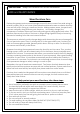
IMPORTANT : Keep this manual for future reference. CARE and MAINTENANCE Wood Furniture Care Perhaps the greatest environmental damage to wood furniture comes from wide swings in relative humidity (RH) in our homes. Wood absorbs and desorbs water as relative humidity rises and falls, and in doing so it swells and shrinks. Making matters worse, it expands and contracts unequally along different grain directions.
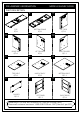
PRE-ASSEMBLY INFORMATION . PART DESCRIPTION A MODEL # AXCLRY-12DCB . . B CL t nt Fro Fro nt Fro nt /A van /A van t t TOP QTY 1 LEFT SIDE QTY 1 BOTTOM FRAME QTY 1 . . CR . DL Fro nt /A van DR t Fro t nt nt /A Fro van t LEFT DIVIDER QTY 1 RIGHT SIDE QTY 1 . . E . G Fro nt nt Fro /A nt van t /A van TOP SHELF QTY 1 MIDDLE SHELF QTY 2 . H van BOTTOM SHELF QTY 1 . IL DIVIDER QTY 9 /A t t .
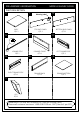
PRE-ASSEMBLY INFORMATION . PART DESCRIPTION K . . L M Warning Label TOP BACK PANEL QTY 1 SHELF QTY 2 . MODEL # AXCLRY-12DCB . N BOTTOM BACK PANEL QTY 1 . O DRAWER FRONT QTY 1 JOINING STRIP QTY 1 . PL . PR . Q RIGHT DRAWER SIDE QTY 1 LEFT DRAWER SIDE QTY 1 R DRAWER BACK QTY 3 DRAWER BOTTOM QTY 1 . S LEG QTY 2 NEED HELP? For help with assembly or if you are missing a part, Please call customer service at 1-866-518-0120 ext.
PRE-ASSEMBLY INFORMATION . HARDWARE DESCRIPTION 1 2 . . . 5 3 . . 9 . . 8 MAGNET AND PLATE QTY 2 SETS . 10 PHILLIPS SCREW M3 X 15mm QTY 8 ALLEN KEY SCREW M6 X 30mm QTY 38 7 PHILLIPS SCREW ROUND HEAD M4 X 15mm QTY 28 ALLEN KEY QTY 1 4 WASHER Ø19 / Ø8 x 1 mm QTY 12 6 . . LOCK WASHER Ø12 / Ø8 x 1.5 mm QTY 12 ALLEN KEY BOLT M8 x 20 mm QTY 12 . MODEL # AXCLRY-12DCB .
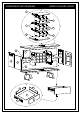
COMPONENTS-KEY DIAGRAM MODEL # AXCLRY-12DCB E / tnorF tnaAv H / tnorF tnaAv F H / tnorF tnaAv G H / tnorF tnaAv / tnorF A N /ontrF tnaA v /ontrF L /ontrF Anavt /ontrF Anavt DL CL CR Anavt DR Anavt IR K K IL M / tnorF tnaA v B S S PR Q R PL O 8/27
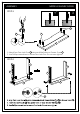
ASSEMBLY MODEL # AXCLRY-12DCB P STEP-1 X 14 14 14 O 1. Attach four Cam Lock Pins 14 into pre-drilled holes on Drawer Front O . 2. Use Phillips screwdriver to secure Cam Lock Pins. Do not over-tighten. STEP-2 PR PR PL PL O O 14 1.AlignCamLockPinswithguideholesandattachDrawerSides 2.InserttwoCamLocks14intoguideholesoneachDrawerSide 3.UsePhilpsscrewdrivertosecureCamLocks.Donotover-tighten. PL,PRtoDrawerFrontO. PL,PR.
ASSEMBLY MODEL # AXCLRY-12DCB STEP-3 5 4 Q R PR PR PL R PL O O 1. Slide Drawer Bottom R firmly into slots on Drawer Sides PL ,PR and Drawer Front O . 2. Align Drawer Back Q with Drawer Bottom R and press firmly into slot . 3. Attach Drawer Back using two Phillip Screws 4 through guide holes on each Drawer Side PL , PR . 4. Use Allen Key 5 to tighten Screws. Do not over-tighten.
ASSEMBLY MODEL # AXCLRY-12DCB STEP-4 11 DR t/ n Fro t/ n Fro ant Av ant Av DL 11 DL DR t t ron van /A F 11 G G t t ron F t van /A 11 t ron van /A F 1. Insert Wood Dowels 11 into guide holes on each part DL , DR , G . 2. Use rubber mallet to tap Dowels 11 into bottom of holes securely. 1/2 length of Dowels should be exposed.
ASSEMBLY MODEL # AXCLRY-12DCB STEP-5 Fro nt Fro nt /A van /A van t t DR DR Fro nt /A van t DL Fro nt /A van t Fro nt /A van t Fro nt DL G /A van t G 4 5 1. Align Wood Dowels with guide holes on Dividers DL , DR and attach Bottom Shelf G to Dividers DL , DR. 2. Use three Allen Key Screws 4 to attach each Divider DL , DR through guide holes. 3. Use Allen Key 5 to tighten Screws. Do not over-tighten.
ASSEMBLY MODEL # AXCLRY-12DCB H STEP-7 F Fro nt /A van t H Fro nt Fro nt /A van /A van t t F 1. Repeat Step - 6 for the rest parts H and F . 4 STEP-8 DR E Fro nt 4 /A van t E DR Fro nt H Fro nt /A van t /A van t DL DL Fro nt /A van t 4 5 1. Align Wood Dowels with guide holes on Top Shelf E and attach Top Shelf E to Dividers H . 2. Use three Allen Key Screws 4 to attach Top Shelf E through guide holes. 3. Use Allen Key 5 to tighten Screws. Do not over-tighten.
ASSEMBLY MODEL # AXCLRY-12DCB 11 STEP-9 Fro nt /A van t B 11 11 Fro nt /A van t B 11 Fro nt CL CR Fro /A van t nt t /A van t CR nt Fro van /A CL 1. Insert Wood Dowels 11 into guide holes on each part B , CL , CR . 2. Use rubber mallet to tap Dowels 11 into bottom of holes securely. 1/2 length of Dowels should be exposed.
ASSEMBLY DL Front / Avant Front / Avant Front / Avant STEP-10 MODEL # AXCLRY-12DCB DR B 1. Align Wood Dowels with guide holes on Bottom Frame B and attach Dividers DL , DR to Bottom Frame B . DL Front / Avant Front / Avant 4 DR B 5 2. Use six Allen Key Screws 4 to attach Bottom Frame B through guide holes. 3. Use Allen Key 5 to tighten Screws. Do not over-tighten.
ASSEMBLY STEP-11 MODEL # AXCLRY-12DCB CL Front / Avant Front / Avant Front / Avant Front / Avant B CR 1. Align Wood Dowels with guide holes on sides CL , CR and attach Sides CL , CR to Bottom Frame B . CL Front / Avant 4 B 4 Front / Avant Front / Avant Front / Avant 5 CR 2. Use six Allen Key Screws 4 to attach Bottom Frame B through guide holes. 3. Use Allen Key 5 to tighten Screws. Do not over-tighten.
ASSEMBLY MODEL # AXCLRY-12DCB STEP-12 B Front / Avant Front / Avant DL Front / Avant Front / Avant DR Front / Avant Front / Avant A Front / Avant CR CL 4 5 CR A 4 DR B DL CL 4 5 4 1. Align Wood Dowels with guide holes on Top A and attach parts CL , CR , DL , DR to Top A . 2. Use three Allen Key Screws 4 to attach each part CL , CR , DL , DR through guide holes. 3. Use Allen Key 5 to tighten Screws. Do not over-tighten.
ASSEMBLY MODEL # AXCLRY-12DCB P STEP-13 5 X 1 2 3 S S B 1. Attach Legs S to Bottom Frame B . 2. Use twelve Allen Key Bolts 1 , twelve Lock Washers 2 and twelve Washers 3 to secure part B and S (six Bolts, six Lock Washers and six Washers on each Leg). 3. Use Allen Key 5 to tighten Bolts. Do not over-tighten.
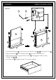
ASSEMBLY MODEL # AXCLRY-12DCB STEP-14 Warning Label NOTE: The screwdriver is not included in the hardware pack. Fro nt /A va nt L 6 N Fro nt M /A va nt L M N M 1. Attach the Top Back Panel L to back frame by using Phillips Screws 6 . Only 1st top row of screws to be screwed in advance. 2. Insert the Bottom Back Panel M into the slot of Plastic Joining Strip N . 3. Insert the entire set of Step 2 into bottom edge of Top Back Panel L and attach both panels L , M with screws 6 .
ASSEMBLY MODEL # AXCLRY-12DCB STEP-15 IL 10 12 IR 1. Attach Adjustable Hinges 12 to Doors IL , IR using Phillips Screws 10 into guide holes on Doors IL , IR .
ASSEMBLY MODEL # AXCLRY-12DCB STEP-16 9 7 9 DR DL CR 7 IR CL IL 12 10 IL CL DL DR CR IR 1. Attach Adjustable Hinges 12 on Doors IL , IR to Sides CL , CR using Phillips Screws 10 into guide holes on Sides CL , CR . 2. Attach Magnets 7 using Phillips Screws 9 into guide holes on Left Divider DL and Right Divider DR . 3. Use Phillips screwdriver to snugly tighten screw.
ASSEMBLY MODEL # AXCLRY-12DCB STEP-17 IMPORTANT NOTE: 10 II I Tighten the Screw marked II to fasten hinge. The door may need to be adjusted so that all the spaces between the door and the unit sides are equal. To adjust, follow instructions: 1. Side adjustment 4 mm To move the door towards the side panel, loosen screw I and tighten screw II . To move the door away from the side panel, loosen screw II and tighten screw I . 2.
ASSEMBLY MODEL # AXCLRY-12DCB STEP-18 shelf level 1 shelf support anti - tipping 8 shelf level 2 shelf level 3 K 8 K K K 1. Use four Shelf Supports 8 for each Shelf K in desired location . 2. Two Shelf Supports 8 may be used on back top of each Shelf K as a tipping restraint.
ASSEMBLY MODEL # AXCLRY-12DCB STEP-19 P X 1. Insert assembled drawer into glides on assembled sideboard.
FURNITURE TIP OVER RESTRAINT ASSEMBLY WARNING Serious or fatal crushing injuries can occur from furniture tip-over. If the furniture tip over restraint kit is not in the box, please contact our customer service department in order to obtain another kit before using the furniture. STEP-20 NOTE: The screwdriver is not included in the hardware pack.
FURNITURE TIP OVER RESTRAINT ASSEMBLY Furniture Tip Over Restraint Instructions: 1. Attach one of the mounting brackets securely to the back edge of the furniture. Use the shorter screw. x P 2. Determine where furniture is to be placed and mark location on the wall for mounting bracket screw hole approximately 2 inches below the bracket mounted to the furniture. P x 3. 4. 5. 6. 7. Drill a 3/16 inch hole in the wall.
TM ® SIMP HOME LIFE BY DESIG N TM WARRANTY Thank you for purchasing a Simpli Home – Wyndenhall – Brooklyn + Max product. These products have been made to demanding, high-quality standards and are guaranteed for domestic use against manufacturing faults for a period of 12 months from the date of purchase. This warranty does not affect your statutory rights. In case of any malfunction of your product (failure, missing parts, etc.) please contact us at our toll free service line at 1-866-518-0120 ext.