Sub-Frame Hitch Installation Instructions Mfg. No. 1694286 For Prestige / 1800 / 2800, Conquest / 1700 / 2700, & Broadmoor / 1600 / 2600 Series Tractors This kit is required when installing front mounted snowthrowers.
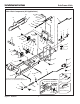
Installation Instructions Sub-Frame Hitch Main Hitch Components (All Applications) 28 29 27 30 29 25 41 33 39 38 40 37 36 35 42 1 3 32 28 27 32 43 2 33 25 33 25 33 29 28 25 25 27 26 25 29 27 34 30 4 28 28 27 5 31 22 6 28 27 26 25 22 24 7 9 8 23 9 9 10 16 15 17 13 18 21 Front Hole for Dozer Applications Rear Hole for Snowthrower Applications Front Pulley - Two-Stage Snowthrower Application 14 11 13 29 44 12 51 26 25 Figure 1.
Installation Instructions Sub-Frame Hitch Ref 1 2 3 4 5 6 7 8 9 10 11 12 13 14 15 16 17 18 19 20 21 22 23 24 25 26 27 28 29 30 31 32 33 34 35 36 37 38 39 40 41 42 42 43 44 Part No.
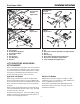
Installation Instructions Sub-Frame Hitch NOTE: Please read through these instructions and the instructions of any other attachments before beginning installation. F Broadmoor / 1600 / 2600 Series WARNING B C E D Before beginning any service work turn off the PTO, set the parking brake, turn off the ignition, and disconnect the spark plug wire(s). INITIAL ASSEMBLY Assemble Hitch 1. Attach the support clamp (C, Figure 2) and hook assembly (B) to the hitch.
Installation Instructions Sub-Frame Hitch Snowthrower & Dozer Applications A C B E D A B Figure 4. Assemble Lift Rod A. Lift Rod C. Spring B. Set Collar D. Rod Guide A C B B D Mower Applications G Figure 5. Early/Later Lift Links A. Early Model Lift Link B. Later Model Lift Link A Assemble Lift Rod 1. Install the set collars (B, Figure 4), spring (C), and rod guide (D) on the lift rod (A) as shown. Final adjustment of the set collars will be made after the hitch and attachment are installed.
Installation Instructions Sub-Frame Hitch A B C D Figure 8. Install Hitch A. J-Hooks B. Hitch Rod C. Hook D. Clamp Plate Install Hitch 1. Slide the hitch under the tractor. 2. Raise the rear of the hitch and place the hook (C, Figure 8) over the lift shaft. 3. Connect the front of the hitch to the tractor J-hooks (A) using the hitch rod (B) and a safety clip. 4. Push the clamp plate (D) backwards until the hook (C) is snug against the lift shaft. Tighten the clamp plate hardware.
Installation Instructions Sub-Frame Hitch D A B C A C B Figure 10. Install Lift Rod - All Models A. Lift Lever B. Lift Rod C. Clip Figure 9. Install Lift Lever A. Lift Lever B. Lift Shaft C. Safety Clip D. Clevis Pin Install Lift Rod 1. Slide the lift lever (A, Figure 9) onto the end of the tractor lift shaft (B) under the right side footrest. 2. Use the tabs on the lift lever (A) to capture the tractor lift arm. Secure in place with a clevis pin (D) and safety clip (C). 3.
Installation Instructions Sub-Frame Hitch Snowthrower Position B C A D E A. B. C. D. Hitch Rod Lift Lever Extension Lift Link (Manual) Pressure Lock Plate (Hydraulic) E. Hook Figure 12. Normal Installation & Removal REMOVAL NORMAL INSTALLATION 1. Disconnect the lift rod from the attachment and lift lever extension (B, Figure 12). 1. Insert the hook (E, Figure 12) into the back of the hitch. Mount the rear of the hitch on the lift crossshaft. 2.
Installation Instructions Sub-Frame Hitch Snowthrower & Dozer Applications Snowthrower & Dozer Applications E A A B F C D E C B D Mower Applications Mower Applications G A A B F G F E Figure 13. Lift Lock Plate - Hydraulic Lift Models A. Lift Cylinder B. Flat Head Pin (Original) C. Flat Head Pin (New) D. Lock Plate E. Hair Pin Clips F. Lift Shaft Assy. G. Washers C D Figure 14. Lift Link - Manual Lift Models A. Pin B. Rear Hole of Lift Bar (Snowthrower Applications) C. Spacer D.
Installation Instructions Sub-Frame Hitch NOTES MANUFACTURING, INC. 500 N Spring Street / PO Box 997 Port Washington, WI 53074-0997 USA Form No. 1724154-04 Rev. 11/2002 © 2002 Simplicity Manufacturing, Inc.