Simplicity SYSTEM 1003 3H.P. TILLER MFG. NOC. 1600397 TINE EXTENSION KIT MFG. NO, 1800407 FURROW OPENER MFG. NO. 1600373 FORM — 1851763 PRINTED IN U.S.
LIMITED WARRANTY New SIMPLICITY products sold by Simplicity Manufacturing Company are warranted by Allies-Chalmers Corporation (the Company} to be merchantable and free of defects in workmanship and material at the time of shipment from the Company's factory., THERE ARE NO WARRANTIES WHICH EXTEND BEYOND THOSE EXPRESSLY STATED HEREIN.
TABLE OF CONTENTS WARRANTY e SAFETY PRECAUTIONS ACCESSORIES e ASSEMBLING OPERATION ADJUSTMENTS e MAINTENANCE OFF-SEASON STORAGE TROUBLESHOOTING . SPECIFICATIONS Page . Inside Cover BONE A NN PARTS LISTINGS FRAME, HANDLES & WHEELS . ENGINE PULLEY & CONTROL GROUP DRIVE & TINE GROUP FURROW OPENER TINE EXTENSION KIT DECAL LOCATION CONGRATULATIONS! This great new product is engineered with imagination and built with integrity to assure you maximum service and performance for years to come.
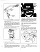
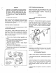
ACCESSORIES TINE EXTENSION SET (Mfg. NO. 1800407} See Figure 1. The extension set consists of a left and right sine assemblies with mounting pins and hairpin clips. Mount long hub of extension over outside end of standard tine assembly and secure assemblies together with pin and hairpin clip. Be sure sharpened edges of tines on top face forward. The extension set increases effective tilling width to 31-1/4 inches. RH. TINE PIN AND HAIRPIN CLIP LONG HUB INWARD Figure 1. FURROW OPENER, 8-INCH (Mfg. No.
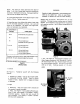
THROTTLE CABLE S~ THROTTLE LEVER Figure 4. b. Be sure throttle control cable is secured along right handle with a cable clip, ¢ See Figure 5. Route cable under right side of belt cover, along right side of engine, and up between fuse tank racket and starter. Install control wire on throttle control lever {A). Throttle control lever must be down and the governor spring relaxed. d. Loosen clamp resew on fuel tank bracket and install throttle cable in clamp. Tighten clamp screw. Figure 5.
NOTE: The depth bar setting determines the depth of tilling. To till 4 10 6 inches deep, install bar taunting pin in second or third hot from the 1op. The deeper depth bar is set into soil, the deeper tines will dig. 8. Loosen each wheel scraper nut and adjust scraper to clear wheel by cinch. Tighten scraper nut. 8. Depending upon what tilling width desired, install right and left tine blade assemblies as follows. Use a pin and cotter pin for installation.
d. A Furrow Opener blade is available for use in digging furrows for crops which are planted in rows, such as potatoes. See Accessories section of this manual. 7™ 3. Depth Bar See Adjustments section of this manual. 4, Wheels 3. Stopping See Figure 7. Be sure wheels are mounted in the LOWER 2 See Figure 11. Push stop switch against end of spark holes of the frame support. plug. b.
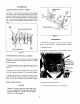
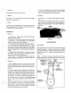
CULT H 1. When clutch disengaged (handle released), idler pulley should be no closer than from frame and all belt stops must be firmly gripping the drive belt. 2. When clutch engaged {handle compressed}, tidier pulley must press in on belt enough to remove belt from contact with belt stops. Approximately clearance between belt stop and belt should be maintained {See Belt Stop Adjustment. 3. See Figure 6.
: St CAUTION DAMAGE TO THE WORM GEAR DRIVE WHICH RESULTS FROM USE OF ANY LUBRICANT OTHER THAN A SPECIAL WORM GEAR OIL WILL AUTOMATICALLY INVALIDATE THE WARRANTY. (See hack cover for Special Work Gear Oil Part Number), d. Tighten filler plug securely. NOTE: The worm drive housing may become quite warm while operating. This is completely normal and no harm to gears will scour if the housing is Kept filed as specified with the special worm gear oif. EVERY 25 HOURS OF OPERATION 1, Change engine oil.
4. While engine is still warm, drain oil from crankcase. See Maintenance section of this manual. Refill with fresh oil. 5. Remove spark plug, pour ane ounce {2 or 3 tablespoons) of SAE 30 oil into cylinder and crank slowly to distribute oil. Replace spark plug. 6. Clean dirt and chaff from cylinder head fins and blower housing. TROUBLESHOOTING IF ENGINE FAILS TO START 1. See Figure 9. Fuel tank may be empty. 2. See Figure 4. Throttle lever is not set halfway between SLOW and FAST position. . : 3.
SPECIFICATIONS MAKE: u M STROKE: 1:3/4 Inches BRIGGS & M CYCLES: 4 W DISPLACEMENT: 7.75 Cu. In.
3H.P. TILLER FRAME, HANDLES & WHEELS ! Ref. Ref. No. | Part No. Oty. Description No.| Part No. Qty. Ascription 1 1600357 1 FRAME ASSEMBLY 21 118498 1 SPRING 2 118469 2 WHEEL & TIRE SAYS.
ROTOTILLER ENGINE PULLEY & CONTROL GROUP TO WORM SHAFT DRIVE AND TINE GROUP N/ Ref. Ref. o No.| Part No. | Qty. Ascription No.| Part No. | Oty.
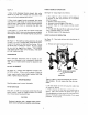
3H.P. TILLER \!Norm Drive Says. consists of Ref. Nos. 1 through 27, Selective fit dus to machining of components, Ref. No.) Part No. Qty. Description No.| Part Ne. Qty. Description ; : ':4332 : 24| 118402 T | COVER 921050 4 | CAP SCREW, Hex hd., 1/43 114396 2 RING, Retaining 20 N.C. x §/8 4 154393 2 CLP, Bearing 2 | 916964 4 LOCK WASHER, 1/4 5 | steads 2 | CONE, Bearing 27 | 930248 1| KEY, Wood ruff, 1/4 x 8 170888 1 SHAFT, Worm 3/'4 7 | 118439 1| key Y., L.H.
3H.P. TILLER MFG. NQ. 1600373 FURROW OPENER Ref. No. | Part No. Oty. Description 1 8271503 1 TOOL HOLDER SAYS. 2 118287 1 SUPPORT ASSEMBLY 3 103010 1 OPENER, Furrow, 8-inch 4 922109 2 BOLT, 3/816x 1-1/4 5 917378 1 WASHER, Flat, 3/8 8 916960 2 NUT, Hex, 3/8 7 118053 1 PIN 8 918196 1 CLIP, Hairpin 3HP, TILLER MFG. NO. 1600407 TINE EXT TENSION KIT Ref. No. [ Part No. Qty. Description 1 1609338 1 BLADE SASSY, Tine left 2 1609334 2 HUB & PLATE SAYS.