
Specifications


I.B. ATS-I005
Page 7
Effective 6/00
SECTION 2: HARDWARE DESCRIPTION
2.1 GENERAL
The purpose of this section is to familiarize the reader
with IQ Transfer hardware, its nomenclature, and to list
the unit’s specifications. The information presented is
divided into the following four parts:
• Operator Panel
• Rear Access Area
• External Hardware
• Specification Summary
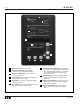
2.2 OPERATOR PANEL
The operator panel, which is normally accessible from
the outside of a panel or door, provides a means for:
• Being alerted to specific conditions
• Receiving functional help
• Programming
• Parameter Monitoring/Selection/Metering
LEDs, a display window, pushbuttons, and a mimic bus
make up the front accessible operator panel (Figure
2-1).
Seventeen individual LEDs are lit when performing or
indicating a specific function. For detailed information on
individual LEDs refer to Paragraph 3.2.
The LED type display window is used to display all IQ
Transfer monitored parameters, setpoints and messages
in easy to read formats. The alpha numeric display is
approximately 0.75 by 4.25 inches and is able to display
up to eight characters at a time. For details concerning
the kind of information that can be viewed in the display
window refer to Paragraph 3.3.
The front operator panel supports six long-life mem-
brane pushbuttons. Pushbuttons accomplish their func-
tion when pressed and released. Refer to Paragraph 3.4
for information concerning the function of specific push-
buttons.
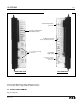
2.3 REAR ACCESS AREA
The rear access area of the IQ Transfer is normally
accessible from the rear of an open panel door
(Figure 2-2).
All wiring connections to the IQ Transfer are made at the
rear of the chassis. For the sake of uniform identification,
the frame of reference when discussing the rear access
area is facing the back of the IQ Transfer with the panel
door open. The communication module port, for exam-
ple, is located on the upper right rear of the unit. The
Run/Program Switch, used to determine the IQ Transfer
Mode, is located in the lower right near the control power
inputs. Detailed information relative to any connection
made to the rear access area is presented in Section 4
entitled “Operation.”
2.3.1 LEFT REAR OF CHASSIS
The left rear of the chassis provides self locking female
connectors J1, J2 and J3 for voltage monitoring of
Source 1 (S1), Source 2 (S2) and the Load respectively.
Terminal block J4 provides DC wetted connections for
various functional inputs. See Paragraph 4.3 for more
information on input functionality.
2.3.2 RIGHT REAR OF CHASSIS
The right rear of the chassis provides a port that will
accept the D-sub male connector of the optional
Communication Module (PONI). A self locking female
connector J7 is provided for Sources 1 and 2 control
power input.
Customer programming is provided through the
Program/Run Toggle Switch. While the switch is in the
Program position, the IQ Transfer continues to operate
in keeping with previously programmed setpoints.
Terminal block J5 provides dry relay contacts for prima-
ry control outputs. Physically these relays are comprised
of two latching Form A relays for generator start con-
tacts, and seven conventional coil Form C relays neces-
sary to complete the electrical control function.
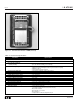
2.4 EXTERNAL HARDWARE (COMMUNICATION
MODULE)
External hardware is viewed as any optional device
mounted directly to or remotely from the IQ Transfer,
such as a communication module. Communications is
made possible by mounting a small, addressable com-
munication module (PONI) to the back of the IQ
Transfer (Figure 2-3) or in a remote location. Since the
IQ Transfer is always supplied with a communications
port, a PONI can be easily retrofitted to the IQ Transfer
at any time. It is recommended that the control
power to the IQ Transfer be removed prior to con-
necting or disconnecting a PONI. When using the
INCOM PONI on the IQ Transfer, the PONI function
switches should be set to either of the Standard PONI