
Specifications


I.B. ATS-I005
Page 8
Effective 6/00
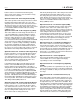
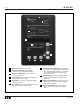
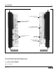
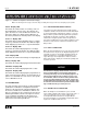
Figure 2-1 IQ Transfer Operator Panel
IQ Transfer Faceplate (UV Resistant)
Operational Mode LEDs (highlighting IQ
Transfer’s present operational condition)
System Status Mimic Bus (easy to read and
understand LED type)
Display Window (easy to read monitored parame-
ters, setpoints and messages)
Display LEDs (seven LEDs to identify the Display
Window Information)
Help Pushbutton (provides English language help
information in any operational mode)
Increase/Decrease Pushbuttons (used individually,
pushbuttons move displayed information/setting
up or down through all possibilities – used simulta-
neously while viewing historical logged values,
values reset to zero)
Step Pushbutton (used to step through different
available information within the category being
displayed)
Display Select Pushbutton (used to move the dis-
play through the categories represented by the 7
LEDs under the display)
Engine Test Pushbutton (pushed and released
twice to initiate a self test in Run or Program
Modes
1
2
3
4
5
6
7
8
9
10
1
2
3
4
5
6
7
8910