
Specifications


I.B. ATS-I005
Page 11
Effective 6/00
Test Mode LED
This LED is lit red upon entering the Test Mode. The
Test Mode can only be entered with the LEDs below the
display window not lit. When a test is initiated, the
Status LED lights. Both LEDs will turn off upon the suc-
cessful completion of a test cycle.
Program Mode LED
This LED is lit red when the Run/Program switch on the
rear of the chassis is in the Program position. This con-
dition permits programming of control setpoints. When
the setpoints LED is lit indicating that existing setpoints
can be changed, the Program Mode LED blinks.
Source 1 Available - Status LED
This LED is lit amber if Source 1 meets the criteria for
programmed Source 1 setpoints.
Source 1 Preferred - Status LED
This LED is lit red if Source 1 is the preferred source
choice.
Source 1 Connected - Status LED
This LED is lit green if Source 1 is connected. This is
accomplished by sensing the Source 1 breaker via the
S1 closed auxiliary contact.
Source 2 Available - Status LED
This LED is lit amber if Source 2 meets the criteria for
programmed Source 2 setpoints.
Source 2 Preferred - Status LED
This LED is lit red if Source 2 is the preferred source
choice.
Source 2 Connected - Status LED
This LED is lit red if Source 2 is connected. This is
accomplished by sensing the Source 2 breaker via the
S2 closed auxiliary contact.
Load Energized - Status LED
This LED is lit red if the load is connected to a source
that is available.
LOAD ENERGIZE LED IS NOT A POSITIVE INDICA-
TION THAT VOLTAGE IS NOT PRESENT ON THE
LOAD TERMINALS.
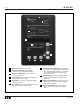
SECTION 3: OPERATOR PANEL
3.1 GENERAL
The operator panel, which is normally accessible from
the outside of a panel or door, provides a means for
being alerted to specific conditions, receiving functional
help, programming, and parameter monitoring/selection
(Figure 2-1). For the purpose of familiarization, the
panel is divided into three sub-sections and discussed
individually:
• LEDs
• Pushbuttons
• Display Window
With respect to their use in this document and as
they relate to automatic transfer switch operation,
the words “Cycle” and “Event” are defined as fol-
lows:
Cycle –A complete operation from Normal to
Emergency to Normal.
Event –A failure resulting in some type of switch
and/or switch intelligence action.
Refer to Appendix D for an overall view of IQ
Transfer operations in the form of a Menu Tree.
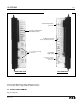
3.2 LEDS
LEDs are used to indicate the device’s mode of operation,
the status of the system, and the operations and/or condi-
tions of displayed functions. Three LEDs at the top of the
IQ Transfer provide a quick snapshot of the unit’s status
(Mode). Seven LEDs, just above the display window, indi-
cate which portions of the mimic bus are active, and the
actual status of both sources and load. The remaining
seven LEDs, just below the display window, are lit to indi-
cate the identity of information being displayed.
Automatic Mode LED
This LED blinks green indicating that the IQ Transfer is
operating and providing the transfer switch control func-
tion in keeping with programmed setpoints. If the LED is
not lit or is on continuously, a problem may be indicated.
NOTICE
NOTICE
!
CAUTION