
Specifications


3.3.1 RUN/PROGRAM TOGGLE SWITCH
The right rear mounted Run/Program Toggle Switch
establishes whether the IQ Transfer is in the Run Mode
or the Program Mode. Normally the switch is set in the
Run position to permit normal programmed operations.
Programmed setpoints can only be altered with the
switch in the Program position. Altered setpoints are
stored and establish the new operating conditions of the
IQ Transfer only after the switch is moved back to the
Run position.
3.3.2 HELP PUSHBUTTON
When the Help Pushbutton is pressed and released with
the IQ Transfer in any mode, an English language mes-
sage will scroll across the display. Pushing and releas-
ing the pushbutton a second time will abort the mes-
sage. Messages and explanations relative to what is
being viewed in the display are intended to prompt and
assist the operator.
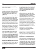
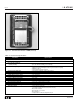
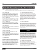
Pressing and Releasing the Help Pushbutton with
the IQ Transfer display window blank causes all of
the front panel LEDs to momentarily light before
scrolling a message across the display (Figure 3-1).
The message indicates the software version, revi-
sion number, and an encoded catalog number that
reveals to Cutler-Hammer what specific options are
included with this particular unit. The customer may
be asked for this information by Cutler-Hammer dur-
ing a troubleshooting or return process.
3.3.3 ENGINE TEST PUSHBUTTON
When the Engine Test Pushbutton is pressed and
released twice with the IQ Transfer in the status state, a
self-test is initiated. This test can be initiated and
accomplished while in the Run or Program Modes.
Pressing the Engine Test Pushbutton again while in the
engine run condition aborts the test.
Figure 3-1 Software and Options Identification Display
Note: The entire Figure 3-1 message is shown for clarity, in actuality the message scrolls across the display as space permits.
NOTICE
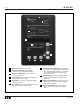
Status - Display LED
This LED is lit red when action is occurring, such as a
timer timing down, and one of the other display cate-
gories has not been selected. When the action is com-
pleted, the display goes blank and the LED turns off.
The Status position is the default position of the display.
Source 1 - Display LED
This LED is lit green when displaying Source 1 voltage,
frequency, and status information. The LED also lights
when displaying specific Source 1 setpoint information.
Source 2 - Display LED
This LED is lit red when displaying Source 2 voltage,
frequency, and status information. The LED also lights
when displaying specific Source 2 setpoint information.
Load - Display LED
This LED is lit red when load voltage is being displayed.
History - Display LED
This LED is lit red when displaying historical information.
Time/Date - Display LED
This LED is lit red when displaying the time or date.
Setpoints - Display LED
This LED is lit red when displaying the programmed set-
points of the IQ Transfer. When a specific displayed set-
point is associated with one of the sources, the specific
source LED will also be lit.
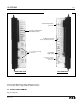
3.3 PUSHBUTTONS
The front operations panel supports six blue membrane
pushbuttons. Pushbuttons accomplish their function
when pressed and released. Certain pushbuttons, like
the Increase and Decrease Pushbuttons, will also con-
tinue to scroll if they are pressed and not released. The
Run/Program Switch, located on the right rear chassis,
is not a membrane pushbutton. It will, however, be
addressed in this section since it is required to move
between the Run and Program Modes.
I.B. ATS-I005
Page 12
Effective 6/00