Parts Manual Large Frame Walk-Behind Snowthrowers 9.5HP Snowthrowers Mfg. No. Description 1694589 1694597 9560E, 9.5HP Snowthrower 9560M, 9.5HP Snowthrower (CE) 10HP Snowthrowers Mfg. No. Description 1694590 1694598 1060E, 10HP Snowthrower 1060M, 10HP Snowthrower (CE) 11HP Snowthrowers Mfg. No. Description 1694591 1694599 1170E, 11HP Snowthrower 1170M, 11HP Snowthrower (CE) 12HP Snowthrowers Mfg. No.
Table Of Contents PRODUCT COMPONENTS PAGES Handles and Controls Group - 1060, 1170, 1280 & 1390 Models ...................................................................... Handles and Controls Group - 9560 Models ....................................................................................................... Engine and Frame Group with Power Boost ....................................................................................................... Engine and Frame Group without Power Boost ....
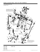
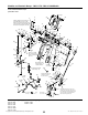
Handles and Controls Group - 1060, 1170, 1280 & 1390 Models 986724 NOTE: Unless noted otherwise, use the standard hardware torque specification chart. 11 10 2 1 Linkage adjustment for traction and auger drive with power boost: with drive levers engaged, the bottom end of lower rods (Ref. 40 & 66) should be flush with bottom of springs (Ref. 39 & 68).
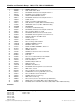
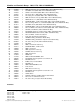
Handles and Controls Group - 1060, 1170, 1280 & 1390 Models REF NO PART NO.
Handles and Controls Group - 1060, 1170, 1280 & 1390 Models 986724 NOTE: Unless noted otherwise, use the standard hardware torque specification chart. 11 10 2 1 Linkage adjustment for traction and auger drive with power boost: with drive levers engaged, the bottom end of lower rods (Ref. 40 & 66) should be flush with bottom of springs (Ref. 39 & 68).
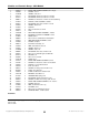
Handles and Controls Group - 1060, 1170, 1280 & 1390 Models REF NO PART NO.
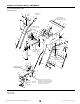
Handles and Controls Group - 9560 Models 986728 NOTE: Unless noted otherwise, use the standard hardware torque specification chart. 8 9 Apply adhesive to secure grips. 10 11 12 6 Must slide freely in dash assembly (Ref 13). Apply lubricant as required. 7 17 4 Insert shift rod (Ref. 58) into outter hole of Ref. 64. 5 65 3 19 14 13 63 64 54 18 16 15 66 35 67 21 56 20 1 12 54 63 2 62 23 61 58 68 56 57 22 60 28 25 16 59 24 26 29 57 56 27 Shift rod assembly (Ref.
Handles and Controls Group - 9560 Models REF NO PART NO.
Handles and Controls Group - 9560 Models 986728 NOTE: Unless noted otherwise, use the standard hardware torque specification chart. 8 9 Apply adhesive to secure grips. 10 11 12 6 Must slide freely in dash assembly (Ref 13). Apply lubricant as required. 7 17 4 Insert shift rod (Ref. 58) into outter hole of Ref. 64. 5 65 3 19 14 13 63 64 54 18 16 15 66 35 67 21 56 20 1 12 54 63 2 62 23 61 58 68 56 57 22 60 28 25 16 59 24 26 29 57 56 27 Shift rod assembly (Ref.
Handles and Controls Group - 9560 Models REF NO PART NO. 45 46 47 48 49 50 51 52 53 54 55 56 57 58 59 60 61 62 63 64 65 66 67 68 1960294 1611911 1931333 1960684 2816168 1668186 1725283 1718593 1918452 1722460 1666255 1960685 1931317 1726304 1726734 1960705 1668523 1924361 1668524 1720240 1715123 1960074 1668185 1960686 QTY.
Engine and Frame Group with Power Boost 986732 NOTE: Unless noted otherwise, use the standard hardware torque specification chart. 17 Position idler pulley (Ref. 14) at center of slot in clutch arm (Ref. 10). 9 21 19 14 15 20 Hook one end of spring (Ref. 16) over clutch rod assembly (Ref. 10) between tabs and other end into slot in frame. 18 13 22 23 11 16 24 8 12 10 25 26 Long hub of idler pulley (Ref. 3) to be toward idler arm (Ref. 6).
Engine and Frame Group with Power Boost REF NO PART NO.
Engine and Frame Group with Power Boost 986732 NOTE: Unless noted otherwise, use the standard hardware torque specification chart. 17 Position idler pulley (Ref. 14) at center of slot in clutch arm (Ref. 10). 9 21 19 14 15 20 Hook one end of spring (Ref. 16) over clutch rod assembly (Ref. 10) between tabs and other end into slot in frame. 18 13 22 23 11 16 24 8 12 10 25 26 Long hub of idler pulley (Ref. 3) to be toward idler arm (Ref. 6).
Engine and Frame Group with Power Boost REF NO PART NO. QTY.
Engine and Frame Group without Power Boost 986730 NOTE: Unless noted otherwise, use the standard hardware torque specification chart. 17 Position idler pulley (Ref. 14) at center of slot in clutch arm (Ref. 10). 9 21 19 14 15 20 Hook one end of spring (Ref. 16) over clutch rod assembly (Ref. 10) between tabs and other end into slot in frame. 18 13 22 23 11 16 24 8 12 10 25 26 Long hub of idler pulley (Ref. 3) to be toward idler arm (Ref. 6).
Engine and Frame Group without Power Boost REF NO PART NO.
Engine and Frame Group without Power Boost 986730 NOTE: Unless noted otherwise, use the standard hardware torque specification chart. 17 Position idler pulley (Ref. 14) at center of slot in clutch arm (Ref. 10). 9 21 19 14 15 20 Hook one end of spring (Ref. 16) over clutch rod assembly (Ref. 10) between tabs and other end into slot in frame. 18 13 22 23 11 16 24 8 12 10 25 26 Long hub of idler pulley (Ref. 3) to be toward idler arm (Ref. 6).
Engine and Frame Group without Power Boost REF NO PART NO. QTY.
Auger and Impeller Group 985466 NOTE: Unless noted otherwise, use the standard hardware torque specification chart. 4 End of hub to be flush with end of rolled down shaft (Ref. 9). 1 2 Torque to 30 -34 ft-lbs. 40 - 46 Nm. 5 10 7 6 2 14 16 10 17 10 18 12 19 9 Impeller to be positioned against bearing before tightening set screw. 13 20 Marked side of worm gear must contact against left thrust washer to assure proper gear mesh. Torque to 18-21 ft-lbs. 24 - 28 Nm.
Auger and Impeller Group REF NO PART NO. 1 2 3 4 5 6 7 8 9 10 11 12 13 14 15 16 17 18 19 20 21 22 23 24 25 26 27 27 27 28 28 28 29 1679293 1928721 1612187A 1960474 1612093 1612149 1612127 2836098 1612129 2818312 1612111 1612142 2168111 2118118 1923358 1612137 1612124 2118315 1612117 2830246 1612141 1612136 1668971 1960346 1668344 1918447 1718782A 1718784A 1718786A 1718783A 1718785A 1718787A 2821133 QTY.
Auger Housing and Chute Group - 38" Models 986720 NOTE: Unless noted otherwise, use the standard hardware torque specification chart. 11 10 9 8 22 21 13 25 14 7 20 12 23 6 18 5 15 19 4 Plastic washer (Ref. 3) goes between chute and deflector. 17 16 3 2 24 1 47 Mount cable bracket (Ref. 23) on right hand side of handle using shift control bracket hardware. When installing cable, make sure it does not come into contact with muffler.
Auger Housing and Chute Group - 38" Models REF NO PART NO.
Auger Housing and Chute Group - 38" Models 986720 NOTE: Unless noted otherwise, use the standard hardware torque specification chart. 11 10 9 8 22 21 13 25 14 7 20 12 23 6 18 5 15 19 4 Plastic washer (Ref. 3) goes between chute and deflector. 17 16 3 2 24 1 47 Mount cable bracket (Ref. 23) on right hand side of handle using shift control bracket hardware. When installing cable, make sure it does not come into contact with muffler.
Auger Housing and Chute Group - 38" Models REF NO PART NO. 45 46 47 48 49 50 1723902C 1921332 1715787C 1666613 1717477A 1930659 QTY. DESCRIPTION 1 4 2 3 1 3 HOUSING AND IMPELLER ASSEMBLY, 38" CAPSCREW, Hex Head, 5/16-18 x 3/4 G5 CUTTER, Drift, 1/4" Thick, 20LG HOLD DOWN, Chute GEAR, Chute NUT, Retainer Speed, 5/16-18 Footnotes The above parts group applies to the following Mfg. Nos.: 1694593 - 1390E 1694601 - 1390M © Copyright 2005 Simplicity Manufacturing, Inc. All Rights Reserved.
Auger Housing and Chute Group - 9560, 1060, 1170 & 1280 Models 986713 NOTE: Unless noted otherwise, use the standard hardware torque specification chart. 21 Decal must cover gap at hinge pivot. 20 11 25 5 14 12 4 19 22 7 6 17 18 13 3 2 Plastic washer (Ref. 2) goes between chute and deflector. 14 16 8 1 15 Mount cable bracket (Ref. 22) on right hand side of handle using shift control bracket hardware. 41 9 10 When installing cable, make sure it does not come into contact with muffler.
Auger Housing and Chute Group - 9560, 1060, 1170 & 1280 Models REF NO PART NO. QTY.
Auger Housing and Chute Group - 9560, 1060, 1170 & 1280 Models 986713 NOTE: Unless noted otherwise, use the standard hardware torque specification chart. 21 Decal must cover gap at hinge pivot. 20 11 25 5 14 12 4 19 22 7 6 17 18 13 3 2 Plastic washer (Ref. 2) goes between chute and deflector. 14 16 8 1 15 Mount cable bracket (Ref. 22) on right hand side of handle using shift control bracket hardware. 41 9 10 When installing cable, make sure it does not come into contact with muffler.
Auger Housing and Chute Group - 9560, 1060, 1170 & 1280 Models REF NO PART NO. 42 42 42 1612184C 1612185C 1612186C QTY. DESCRIPTION 1 1 1 HOUSING AND IMPELLER ASSEMBLY, 24" (Used on 9560 & 1060 Models) HOUSING AND IMPELLER ASSEMBLY, 28" (Used on 1170 Models) HOUSING AND IMPELLER ASSEMBLY, 32" (Used on 1280 Models) Footnotes The above parts group applies to the following Mfg. Nos.
Traction Drive Group 986712 NOTE: Unless noted otherwise, use the standard hardware torque specification chart. Mounted inside of frame. 2 Pack groove with grease. 3 4 1 5 2 3 13 Lubricate with 5W 50 Synthetic oil. 12 Mount to bracket in frame weldment. 6 14 7 Apply loctite (2 places). 8 20 1 Hook end to top left corner slot of frame. 11 10 Apply Loctite and• Torque to 55 - 60 in-lbs. when all parts are against hub. 9 21 18 Mounted outside of frame. 23 19 Mounted outside of frame.
Traction Drive Group REF NO PART NO.
Traction Drive Group 986712 NOTE: Unless noted otherwise, use the standard hardware torque specification chart. Mounted inside of frame. 2 Pack groove with grease. 3 4 1 5 2 3 13 Lubricate with 5W 50 Synthetic oil. 12 Mount to bracket in frame weldment. 6 14 7 Apply loctite (2 places). 8 20 1 Hook end to top left corner slot of frame. 11 10 Apply Loctite and• Torque to 55 - 60 in-lbs. when all parts are against hub. 9 21 18 Mounted outside of frame. 23 19 Mounted outside of frame.
Traction Drive Group REF NO PART NO. 45 46 47 48 49 50 51 52 53 54 55 56 57 58 59 1665521 1666425 1666855 1666001 1720299 1928721 1672595A 1919394 1729254 1720300 1930570 2821133 1720716 2860169 1720305 QTY.
Wheels & Tires Group 986549 NOTE: Unless noted otherwise, use the standard hardware torque specification chart. 1 2 3 4 6 5 7 6 8 4 9 10 The above parts group applies to the following Mfg. Nos.: 1694589 - 9560E 1694590 - 1060E 1694591 - 1170E 1694592 - 1280E 1694593 - 1390E 1694597 - 9560M 1694598 - 1060M 1694599 - 1170M 1694600 - 1280M 1694601 - 1390M © Copyright 2005 Simplicity Manufacturing, Inc. All Rights Reserved.
Wheels & Tires Group REF NO PART NO. 1 2 3 3 4 5 5 6 6 7 7 8 8 9 10 1921978 1919438 1726743 1726745 2172353 1714242 1722762 1727074 1727075 1726742 1726744 1720307 1722761 2153038 1666969 QTY. DESCRIPTION 1 1 1 1 2 1 1 2 2 1 1 1 1 2 1 CAPSCREW, Hex Head 5/16-18 x 2 G5 NUT, Hex Lock ESNA Light 5/16-18 NC-3B WHEEL & TIRE ASSEMBLY, Snow R.H. (Used on 24 & 28 in. Models) WHEEL & TIRE ASSEMBLY, Snow R.H. (Used on 32 & 38 in. Models) VALVE STEM & CAP ASSEMBLY, Air HUB, Wheel R.H.
Decal Group 986738 NOTE: Unless noted otherwise, use the standard hardware torque specification chart. 1 3 2 Free Hand Locked Free Hand Unlocked WARNING Au ger Enga ge AVOID SERIOUS INJURY OR DEATH 1727020 Traction Enga ge Traction Disengage • Read the operator's manual for operating and safety • Always direct discharge chute so as to avoid instructions. injury to persons or damage to property. • Do not defeat the safety features of control.
Decal Group REF NO PART NO. 1 1 2 3 3 4 5 6 6 7 8 9 9 9 9 9 10 10 11 11 12 13 14 14 15 16 1726945 1727022 1715557 1726946 1727023 1715558 1722867 1726947 1727024 1714245 1714246 1727019 1725376 1725377 1725378 1724075 7071880 1727207 1716532 1727208 * 1725507 * * 1720454 * QTY. DESCRIPTION 1 1 1 1 1 1 1 1 1 1 1 1 1 1 1 1 1 1 1 1 1 1 1 2 1 1 DECAL, Dashboard EZ Turn L.H. (Tube Handle Models Only) DECAL, Dashboard EZ Turn L.H.
Headlight Group 986371 NOTE: Unless noted otherwise, use the standard hardware torque specification chart. 1 7 2 4 5 6 3 Existing Hardware The above parts group applies to the following Mfg. Nos.: 1694589 - 9560E 1694590 - 1060E 1694591 - 1170E 1694592 - 1280E 1694593 - 1390E 1694597 - 9560M 1694598 - 1060M 1694599 - 1170M 1694600 - 1280M 1694601 - 1390M © Copyright 2005 Simplicity Manufacturing, Inc. All Rights Reserved.
Headlight Group REF NO PART NO. 1 2 3 4 5 6 7 1725291 1701011 2834683 1709256A 1917372 1725292C 1931333 QTY. DESCRIPTION 1 2 1 1 1 1 1 HEADLIGHT ASEMBLY TIE, Self Locking CLIP, Wire LOCKWSHER, 5/16 NUT, Hex, 5/16-18 BRACKET CARRIAGE BOLT, 5/16-18 x 3/4 Footnotes The above parts group applies to the following Mfg. Nos.
Hardware Identification & Torque Specifications Common Hardware Types Torque Specification Chart Hex Head Capscrew FOR STANDARD MACHINE HARDWARE (Tolerance ± 20%) Washer Hardware Grade Lockwasher Carriage Bolt No Marks SAE Grade 2 Hex Nut Size Of Hardware Standard Hardware Sizing 8-32 8-36 10-24 10-32 1/4-20 1/4-28 5/16-18 5/16-24 3/8-16 3/8-24 7/16-14 7/16-20 1/2-13 1/2-20 9/16-12 9/16-18 5/8-11 5/8-18 3/4-10 3/4-16 7/8-9 7/8-14 1-8 1-12 When a washer or nut is identified as 1/2”, this is the
MANUFACTURING, INC. 500 N. Spring Street / PO Box 997 Port Washington, WI 53074-0997 USA www.simplicitymfg.com © Copyright 2005 Simplicity Manufacturing, Inc. All Rights Reserved. Printed In USA.