Field Guide to Soil Moisture Sensor Use in Florida
The Field Guide to Soil Moisture Sensor Use in Florida was produced for the St. Johns River Water Management District (SJRWMD) by the Program for Resource Efficient Communities (PREC) at the University of Florida (UF). Primary Author................................Brent T. Philpot, MS, Research Associate, PREC Supervising Specialist......................Dr. Michael D.
Table of Contents I. Introduction..........................................................................................................................................................................1 A. The Role of the Modern Soil Moisture Sensor in Florida......................................................................................1 B. University of Florida Research...........................................................................................................................
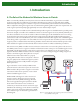
Introduction I. Introduction A. The Role of the Modern Soil Moisture Sensor in Florida Water is an extremely valuable yet seriously stressed resource in Florida. Nevertheless, in-ground, time-controlled irrigation systems that use potable water are standard in the landscapes of a majority of newly built homes. Ideally, homeowners adjust their irrigation controllers in response to seasonal weather patterns.
Introduction Useful Terms Evapotranspiration (ET) – A combination of water transpiration from vegetation and evaporation from the soil and plant surfaces; also known as consumptive use. Field capacity – The moisture remaining in the soil following wetting and gravitational drainage until water has ceased drainage. Irrigation zone – An area in a landscape that is irrigated by a single zone (solenoid) valve; also known as a hydrozone.
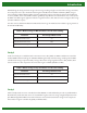
Introduction Rainfall during this study period was average to above average, resulting in high sensor-based water savings. Treatments were compared to a two-day-a-week, time-based irrigation schedule, based on Dukes and Haman (2002a), using no sensor technology. All four SMS controller treatments applied less irrigation water than the time-based schedule with no sensor (Table 1).
Introduction Disclaimer Procedures for proper installation, calibration, and maintenance vary by SMS brand. Generally, each manufacturer’s installation manual provides adequate instructions for effective installation. Installation manuals should be referenced for specific instructions, especially for wiring, calibration, and troubleshooting. Valuable lessons have been learned during testing conducted by the University of Florida (UF) that can provide additional guidance.
Installation II. Installation The four main installation steps are: 1. Establish the sensor location. 2. Install the sensor. 3. Install the controller. 4. Connect the wiring. Step 1: Establish the Sensor Location An SMS is most effective when placed in a location representative of the zone(s) that the sensor is controlling. If multiple sensors are being used in a landscape (i.e., one sensor per zone), each sensor should be placed in an area representative of the specific zone it is controlling.
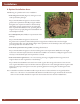
Installation A. Optimal Installation Areas The following are optimal areas for sensor installation: • In the turf grass root zone (Figure 2), if turf grass is used as the representative plant type Purpose: Provide sufficient irrigation to the area with the greatest water requirement. Generally, turf grass will have the highest water requirement relative to other landscape plants.
Installation B. Areas to Avoid – General When establishing the SMS location, certain areas and site conditions should be avoided. INSTALL the sensor at least 5 feet away from: To avoid: • A property line ��������������������������������������������������������������irrigation overspray from a neighbor’s yard • An impervious surface ��������������������������������������������������runoff from impervious surfaces and compacted soil around impervious surfaces • A structure (e.g., house, porch, shed, etc.).
Installation D. Areas to Avoid – Disturbed Sites and Soils In some areas it is difficult to tell if the soil has been, or will be, compacted. Installers should use their best knowledge of the landscape history and projected use to determine the SMS location. If it is known that the soil has been, or will be, compacted in one particular area, the SMS should be installed elsewhere.
Installation In a Typical Landscape Figure 3 depicts a typical residential landscape characterized by large turf grass areas (greater than 60% of the entire landscape) and very few trees. There are many optimal sensor locations in this landscape, and it should be relatively easy to determine the best location within a short period of time. A newly developed landscape of this type will have fill material that must be considered during SMS installation. Figure 3.
Installation In a Florida Water StarSM Landscape Figure 4 depicts a hypothetical Florida Water StarSM (water-efficient) landscape, composed of 60% or less turf grass and 40% or greater planting beds, natural areas, or drought-tolerant ground covers. Reduced turf grass area decreases the number of optimal SMS locations. There are optimal areas in the front yard, but fewer such areas exist throughout the Florida Water StarSM landscape when compared to a typical landscape.
Installation In a Preserved Vegetation Landscape Figure 5 depicts a residential landscape with a high percentage of preserved vegetation. This landscape has more shaded areas, less turf grass, and potentially higher soil moisture content. Because of the landscape layout, the optimal areas for SMS installation might be considered secondary areas in other landscapes. However, the goal is to place the SMS in a representative area.
Installation F. Include SMS Location in New Landscape Plans Specifying the SMS location in the landscape and irrigation design plan prior to installation can help to simplify the installation process and reduce human error in the field. If the location is predefined, the installer will spend less time surveying the landscape to determine an optimal sensor location.
Installation A. Sensor Types Three types of residential sensor probes are now typically available in Florida: (1) flat, (2) node, and (3) rod. Installation procedures vary by type and are described individually in the sections below. 1. Flat Sensor Probes Two types of long, flat sensor probes are commonly found. Sensors with this type of probe often use time domain transmissivity (TDT) to measure soil moisture content.
Installation Flat Probes in Existing Landscapes Two methods can be used to install flat sensors in existing landscapes. Option 1: Bury the SMS probe in a shallow hole by rolling back a square of cut turf grass. 1. Using a square-point ditching shovel, cut a square piece of turf grass sod to the midpoint of the maximum plant root density and just large enough to cover the entire probe (Figure 10). 2. Remove the cut square of turf grass sod by rolling it back to expose the soil below (Figure 11). Figure 10.
Installation 6. Gently compact the turf grass sod, making sure that there are no channels that will allow water to seep in and pool around the SMS probe (Figure 14). Additional soil can be added on top of the sensor location so that it may wash into any remaining gaps. Figure 14. Gently compacting the turf grass area Option 2: Slide the SMS into the sidewall of a hole by cutting the turf grass roots. 1.
Installation 3. Using the manufacturer’s specified orientation, slide the sensor probe into cut area at the midpoint of the maximum turf grass root density (Figure 17). 4. Gently compact the soil above the sensor to ensure that there is sufficient contact between the sensor probes and the soil (Figure 18). Figure 17. SMS probe installed within root zone Figure 18. Compaction of soil around sensor to reduce void space and ensure adequate connection between SMS probe and soil 5.
Installation 2. Node Probes An SMS with node probes should be installed vertically or at a 45-degree angle within the root zone. Sensors with this type of probe typically use granular matrix technology to measure soil moisture. Because this type of sensor might have additional specifications, always refer to the manufacturer’s installation manual. Figure 20 shows a granular matrix sensor (GMS) being installed in a new landscape. Figure 20. SMS node probes in a new landscape installation Figure 21.
Installation 3. Insert the sensor into the side of the trench at a 45-degree angle (see Figure 21). 4. Dig the trench to run the wiring (see section B); make the connections according to the manufacturer’s specifications; and check for proper SMS controller functioning. 5. Replace the plug of turf cut out, completely covering the sensor and keeping the wires at the bottom of the trench. 6. Tamp the replaced turf plug down firmly. 3.
Installation 3. Dig the trench to run wiring (see section B); make the connections according to the manufacturer’s specifications; and check for proper SMS controller functioning. 4. Replace the cut square of turf grass sod. 5. Gently compact the turf grass and soil plug, making sure that there are no channels that will allow water to seep in and pool around the SMS probe. Additional soil can be added on top of the sensor location to fill in any remaining gaps. B.
Installation Manual Digging In Existing Landscapes Two manual digging methods, lift trench and slit trench, can be used for running wiring in existing landscapes. a. Lift Trench Method A lift trench is made by inserting a square ditching shovel at a 45-degree angle to the ground surface and while the soil is lifted, inserting the wiring underneath. This method is appropriate when no conduit is being used and there is little risk of cutting the wire.
Installation b. Slit Trench Method A slit trench is a wedge made in the ground. This method can be slightly more time-consuming than the lift trench method, while also leaving a line of dead turf after installation. However, this method should be used when running wiring through conduit for additional protection (Figure 27). When manually digging a trench, the slit trench method including conduit is recommended. 1. Insert a square ditching shovel into the ground at a 90-degree angle. 2.
Installation Step 3: Install the Controller There are two recommended locations for an SMS controller: • Adjacent to the irrigation timer on an interior wall (e.g., garage) • Adjacent to the irrigation timer in a weatherproof housing on the exterior of the home Note: Do not install the SMS controller outside without a weatherproof housing and ultraviolet (UV) protection from the sun. After determining the SMS controller location, install it on the wall adjacent to the timer.
Installation A. Connect Sensor to the Zone Valve Generally, sensors can be wired either to an irrigation valve or directly to the SMS controller. It is recommended that the SMS be wired to the nearest zone valve, if possible, to facilitate sensor installation in the most representative area. Some sensors must be wired to the last zone valve for the entire system to be controlled by the SMS controller. Wiring configurations vary among brands.
Installation B. Connect SMS Controller to the Irrigation Timer The connections from the SMS controller to the irrigation timer also vary by brand and should always be done according to specifications in the manufacturer’s installation manual. Figures 35 through 38 show a controller being wired to an irrigation controller. 24 Figure 35. Open irrigation timer, exposing wires to be connected to SMS controller Figure 36.
Calibration III. Calibration Step 1: Establish the Controller Set Point Prior to calibration and set point establishment, it is necessary to determine how much water can be held in the root zone where the SMS is located. To achieve this, the installer should saturate the area immediately around the SMS location. Within 24 hours of saturation, the controller will read the soil moisture content, which should be close to field capacity (i.e., no further water drainage below the root zone).
Calibration Step 2: Calibration Always refer to the manufacturer’s specifications for detailed SMS controller calibration procedures. Calibration instructions are brand-specific and cannot be adequately addressed for all systems here in this field guide. Timing With Plant Establishment In new landscapes, plants (including turf grass) are often installed at about the same time as irrigation systems. During root establishment, new plants have their highest water needs.
Calibration Irrigation Controller Scheduling The irrigation controller, not the SMS controller, initiates scheduled irrigation events. It is extremely important that the irrigation controller be set for an irrigation schedule appropriate for the irrigation system, location, plant need, season, and your water management district’s requirements. Appendix B contains recommended irrigation scheduling for Florida turf grasses. To establish the run-time for a particular zone, use the following procedure: 1.
Calibration 28
Maintenance IV. Maintenance SMS control system manufacturers do not specify routine maintenance procedures. A properly working SMS controller should not result in excessive irrigation application. If the system is applying excessive amounts of irrigation, it needs to be inspected by an irrigation contractor. The principle maintenance task described here is monitoring of the irrigation system’s functioning.
Maintenance Dual Meter If an independent water meter is installed to record irrigation consumption, calculating SMS performance is relatively straightforward. The only required calculation is estimation of the irrigated landscape area (square feet). b. Compare to Appendix C Appendix C contains monthly recommended net irrigation volume in gallons by region. Net irrigation is calculated by subtracting average historical rainfall from historical evapotranspiration (ET).
Maintenance B. Other Information Periodic Recalibration SMS controller set points can be increased or decreased periodically to achieve a homeowner’s desired irrigation results. Reasons for this periodic recalibration could be seasonal weather variation, water table variation, improper sensor location, or site alteration. If the system is installed properly and the landscape has not been altered, recalibration is only recommended once a year as part of a routine annual irrigation system maintenance program.
Maintenance 32
Troubleshooting V. Troubleshooting SMS control systems have troubleshooting procedures that are typically model-specific, and operators should always refer to the manufacturer’s installation manual for troubleshooting guidance. Important Reminders • Be certain the sensor is connected to the valve that controls irrigation in the sensor’s location. • Make sure the correct wire is connected to the sensor zone terminal on the irrigation timer.
Troubleshooting 34
Resources VI. References and Resources A. Irrigation Scheduling Augustin, B.J. (2000). Water requirements of Florida turfgrasses. BUL200, Institute of Food and Agricultural Sciences, University of Florida, Gainesville, Fla. Available: http://edis.ifas.ufl.edu/pdffiles/EP/EP02400.pdf. Dukes, M.D., and, D.Z. Haman (2002a). Operation of residential irrigation controllers. CIR1421, Institute of Food and Agricultural Sciences, University of Florida, Gainesville, Fla. Available: http://edis.ifas.ufl.edu/AE220.
Resources 36
Appendixes VII. Appendixes Appendix A: Where to Install a Soil Moisture Sensor (SMS) Prerequisites for Placement • • • • Within the root zone of turf grass In sunniest area possible Within the driest area possible considering all other factors Within the center of an irrigation zone Main Areas to Avoid Away from structures (house, garage, shed, etc.
Appendixes Appendix B: Irrigation Scheduling per Irrigation Event for Florida Turf Grasses (minimum) Season North Central South Season 0.50 inches/hour North Central South 1.50 inches/hour Winter 5 25 50 Winter 0 10 15 Spring 75 110 80 Spring 25 35 25 Summer 80 95 100 Summer 25 30 35 Autumn 55 85 65 Autumn 20 30 20 0.75 inches/hour 1.
Appendixes Appendix C: Monthly Net Irrigation Requirements for Florida Table 1: Monthly Net Irrigation Requirements for North Florida Net Irrigation Requirement (Historical ET – Rainfall) Volume (gallons) of Irrigation per Irrigated Area (square feet) Maximum Application (inches) 1 2,000 4,000 6,000 8,000 10,000 Spring 3.70 4,600 9,200 13,800 18,500 23,000 Summer 3.21 4,000 8,000 12,000 16,000 20,000 Autumn 3.51 4,400 8,800 13,100 17,500 21,900 Winter 1.
Appendixes Table 3: Monthly Net Irrigation Requirements for South Florida Net Irrigation Requirement (Historical ET – Rainfall) Volume (gallons) of Irrigation per Irrigated Area (square feet) Maximum Application (inches) 1 2,000 4,000 6,000 8,000 10,000 Spring 4.12 5,100 10,300 15,400 20,500 25,700 Summer 4.06 5,100 10,100 15,200 20,200 25,300 Autumn 2.96 3,700 7,400 11,100 14,800 18,500 Winter 2.07 2,600 5,200 7,700 10,300 12,900 Annual Total 13.