Parts Manual INTERMEDIATE SNOWTHROWERS ATTACHMENTS & INCLUDING ACCESSORIES 555 SNOWTHROWERS Mfg. No. 1692680 1693161 1693163 1693425 1693646 1693647 Description 555M, 5 HP Manual Start 555M, 5 HP Manual Start 555M, 5 HP Manual Start (Export) 555M, 5 HP Manual Start 555M, 5 HP Manual Start 555M, 5 HP Manual Start (Export) 755 SNOWTHROWERS Mfg. No.
MANUFACTURING, INC. 500 N Spring Street / PO Box 997 Port Washington, WI 53074-0997 USA © Copyright 1999 Simplicity Manufacturing, Inc. All Rights Reserved. Printed In USA.
Table of Contents SNOWTHROWERS..........................................PAGES This Manual Covers The Following Products: Handles and Controls (Early)..............................2 555 SNOWTHROWERS PAGES Handles and Controls (Later) .............................6 Early Models 1692680 1693161 1693163 1693425 555M, 5HP Manual Start 555M, 5HP Manual Start 555M, 5HP Manual Start (Export) 555M, 5HP Manual Start Frame ...............................................................
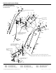
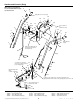
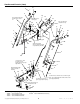
Handles and Controls (Early) NOTE: Unless noted otherwise, use the standard hardware torque specification chart. 8 10 Apply adhesive to secure grip. 6 16 14 15 17 31 18 47 45 Ref. 18 required on slotted holes only. 49 46 4 13 48 30 9 50 12 29 3 11 28 44 3 7 51 54 17 48 2 10 38 55 53 19 1 20 22 52 Shift rod assembly (Ref. 53) must pivot freely on pivot blocks (Ref. 48). Apply adhesive to grip. 21 43 22 5 25 42 24 41 Use washers to shim gear 31 (Ref.
Handles and Controls (Early) REF NO. 1 2 3 4 5 6 7 8 9 10 11 12 13 14 15 16 17 18 19 20 21 22 23 24 25 26 27 28 29 30 31 32 33 34 35 36 37 38 39 40 41 42 43 PART NO.
Handles and Controls (Early) NOTE: Unless noted otherwise, use the standard hardware torque specification chart. 8 10 Apply adhesive to secure grip. 6 16 14 15 17 31 18 47 45 Ref. 18 required on slotted holes only. 49 46 4 13 48 30 9 50 12 29 3 11 28 44 3 7 51 54 17 48 2 10 38 55 53 19 1 20 22 52 Shift rod assembly (Ref. 53) must pivot freely on pivot blocks (Ref. 48). Apply adhesive to grip. 21 43 22 5 25 42 24 41 Use washers to shim gear 31 (Ref.
Handles and Controls (Early) REF NO. 44 45 46 47 48 49 50 51 52 53 54 55 PART NO. 1917421 108512 1715536 1715123 1668524 1918452 1668185 1924361 1921159 1668523 1960074 1922755 QTY. 1 1 1 1 2 1 2 1 4 1 1 1 DESCRIPTION NUT, Jam, 3/8-16 PIVOT ROD & ARM ASSY., Pivot SPRING, Torsion BLOCK, Pivot PIN, Cotter BUSHING WASHER CAPSCREW, Hex Hd. 1/4-20 x 2 1/4 G5 ROD & CLEVIS ASSY. CLIP, Hair Pin WASHER Footnotes: The above parts group applies to the following Mfg. Nos.
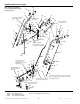
Handles and Controls (Later) NOTE: Unless noted otherwise, use the standard hardware torque specification chart. 10 8 6 14 16 15 Insert shift rod (Ref. 46) into inner hole of Ref. 47. Apply adhesive to secure grips. 17 33 18 48 42 4 Ref. 18 required on slotted holes only. 13 49 28 12 9 44 50 11 31 3 30 42 3 49 7 51 47 17 46 2 32 30 53 44 19 52 20 45 1 22 Shift rod assembly (Ref. 53) must pivot freely on pivot blocks (Ref. 49).
Handles and Controls (Later) REF NO. 1 2 3 4 5 6 7 8 9 10 11 12 13 14 15 16 17 18 19 20 21 22 23 24 25 26 27 28 29 30 31 32 33 34 35 36 37 38 39 40 41 42 43 PART NO.
Handles and Controls (Later) 10 8 6 14 16 15 Insert shift rod (Ref. 46) into inner hole of Ref. 47. Apply adhesive to secure grips. 17 33 18 48 42 4 Ref. 18 required on slotted holes only. 13 49 28 12 9 44 50 11 31 3 30 42 3 49 7 51 47 17 46 2 32 30 53 44 19 52 20 45 1 22 Shift rod assembly (Ref. 53) must pivot freely on pivot blocks (Ref. 49). 32 44 10 45 21 43 22 5 23 42 27 Use washers to shim gear (Ref. 34) as required to insure proper adjustment.
Handles and Controls (Later) REF NO. 44 45 46 47 48 49 50 51 52 53 PART NO. 1916622 1916964 1720238 1720240 1715123 1668524 1668185 1924361 1921159 1668523 QTY. 3 3 1 1 1 2 2 1 1 1 DESCRIPTION NUT, Hex Hd., 1/4-20 LOCKWASHER ROD, Shift, Upper ROD & ARM ASMY, Pivot SPRING, Torsion BLOCK, Pivot BUSHING WASHER CAPSCREW, Hex Hd., 1/4-20 x 2-1/4 ROD & CLEVIS ASSY. Footnotes: The above parts group applies to the following Mfg. Nos.: 1693646 1693647 1693648 555M, 5HP Manual Start 555M, 5HP Manual Start (Exp.
Frame NOTE: Unless noted otherwise, use the standard hardware torque specification chart. 2 1 1 8 Right rear only on 1997 & later models. 7 5 3 1 4 6 3 9 10 1997 & Later Models 1693161 1693162 1693163 1693164 1693425 32 1693426 1693646 1693647 1693648 33 1693649 Engine 31 34 14 29 11 7 11 11 6 12 Top hole. 5 7 6 3 13 6 5 6 27 3 1996 Models 1692680 1692681 1692746 31 15 7 25 29 28 16 26 29 6 17 24 Ref. 19 required on rear engine bolts only. 18 7 19 30 21 Ref.
Frame REF NO. PART NO. QTY.
Engine NOTE: Unless noted otherwise, use the standard hardware torque specification chart. 6 5 4 2 3 1 Torque to 10 - 14 ft-lbs. 8 13 12 Install with hub facing engine. 11 8 1 Torque to 10 - 14 ft-lbs. Leave .18" grip between hex nut and head of cap screw. 9 See Frames Install with hub facing engine. 7 Engine Pulley (Auger) Engine Pulley (Auger) 10 1.
Engine REF NO. PART NO. QTY. 1 2 3 4 5 1921515 1919326 1715136 1920427 * 2 2(1) 1 1 1 5 5 5 6 7 * * * * 1674325 1 1 1 1 1 7 1678692 1 8 9 10 10 11 12 12 13 14 14 1960619 924819 1672735 1720237 920438 1715090 1720313 905850 1715128 1717393 2 1 1 1 1 1 1 1 1 1 15 15 15 1715127 1715591 1720234 1 1 1 DESCRIPTION CAPSCREW, Hex Hd., 5/16-24 x 3/4 WASHER, (Qty. 1 on 1693646 & 1693648) BELT STOP LOCKWASHER-EXTERNAL TOOTH .
Auger Drive and Impeller NOTE: Unless noted otherwise, use the standard hardware torque specification chart. 1 Torque to 9 - 11 ft-lbs. 2 4 3 5 Apply a bead of gasket eliminator into rear seal groove and flat surface just past groove (Ref. 15 & 20). 13 Hub of pulley to face of auger. 2 6 7 9 3 17 18 Torque (Ref. 2) to 9 - 11 ft-lbs. 11 12 8 10 Locate pulley on worm shaft (Ref. 10) so the belt is 1.94" from rear of impeller housing. 14 15 19 16 3 20 17 21 Torque to 9 - 11 ft-lbs.
Auger Drive and Impeller REF NO. 1 2 3 4 5 6 7 8 9 10 11 12 13 14 15 16 17 18 19 20 21 22 23 24 25 26 27 28 29 30 31 PART NO. 1715091 1930540 905123 1960474 1715120 1611789 1666425 936098 1668105 1660240 1670971 1666424 1676027 1923358 1611794 1611784 1676026 1716127 1676024 1611793 960625 1924009 921133 1676328 1676327 1918447 1668344 1960114 927794 1718780 1718781 QTY. 1 2 3 1 1 1 1 1 1 1 1 1 2 6 1 1 2 1 1 1 1 6 2 1 1 2 2 4 2 1 1 DESCRIPTION PULLEY,Auger Drive SETSCREW, Sq. Hd.
Auger Housing and Chute NOTE: Unless noted otherwise, use the standard hardware torque specification chart. Seal must cover openings at hinge pivot. 5 4 Place Ref. 3 between chute and deflector. 3 1 31 32 6 30 2 29 26 7 28 8 9 27 10 11 12 Coat top and bottom of chute ring with grease. 24 34 25 35 13 33 23 14 22 15 Mounts to underside of housing. 16 21 20 18 17 19 The above parts group applies to the following Mfg. Nos.
Auger Housing and Chute REF NO. PART NO. QTY.
Traction Drive NOTE: Unless noted otherwise, use the standard hardware torque specification chart. 1 10 Inside of frame. 11 9 14 15 17 16 13 18 12 Apply loctite & torque to 55 - 60 in-lbs. 13 Coat with Protectokote or rust preventive oil. 12 20 8 5 12 19 Tighten when all parts are tight against shoulder of hub. 9 22 24 23 26 30 Apply anti-seize to both ends. 11 10 Inside of frame. 36 Torque to 18 - 21 ft-lbs. 7 19 29 38 35 4 13 Torque to 10 - 14 ft-lbs.
Traction Drive REF NO. 1 2 3 4 5 6 7 8 9 10 11 12 13 14 15 16 17 18 19 20 21 22 23 24 25 26 27 28 29 30 31 32 33 34 35 36 37 38 39 40 41 42 43 44 45 46 PART NO.
Decals NOTE: Unless noted otherwise, use the standard hardware torque specification chart. 3 WARNING TO AVOID SERIOUS INJURY 3 2 • Read Owner's Manual before operating unit • Never allow children to operate snowthrower • Always direct discharge chute so as yto avoid injury to persons—or damage to property • Stop engine and disconnect spark plug befor removing debris or servicing unit. • Keep all shields and guards in place while running.
Decals REF NO. 1 2 3 4 5 5 6 7 8 9 9 9 10 PART NO. 1715557 1715555 1715556 1715558 1714107 1714108 1716533 1716532 * 1709061 1717431 1720454 * QTY.
Wheels and Tires NOTE: Unless noted otherwise, use the standard hardware torque specification chart. 6 1 2 3 5 4 The above parts group applies to the following Mfg. Nos.: 1692680 1692681 1692746 555M, 5HP Manual Start 755E, 7HP Electric Start 755M, 7HP Manual Start (Exp.) © Copyright 1999 Simplicity Manufacturing, Inc. All Rights Reserved. 1693161 1693162 1693163 555M, 5HP Manual Start 755E, 7HP Electric Start 555M, 5HP Manual Start (Exp.) 22 1693164 1693425 755M, 7HP Manual Start (Exp.
Wheels and Tires REF NO. 1 2 3 4 5 6 PART NO. 1715124 1715126 1715125 1664090 172353 1666969 QTY. 2 2 2 2 2 2 DESCRIPTION WHEEL ASSEMBLY, (Includes Ref. 2-5) TIRE HUB TUBE, Tire VALVE STEM & CAP KLIK-PIN Footnotes: The above parts group applies to the following Mfg. Nos.: 1693426 1693646 1693647 755E, 7HP Electric Start 555M, 5HP Manual Start 555M, 5HP Manual Start (Exp.) TP-400-2001-05-IW-S 1693648 1693649 755M, 7HP OHV Manual Start 755M, 7HP OHV Manual Start (Exp.
Accessories and Attachments NOTE: Unless noted otherwise, use the standard hardware torque specification chart. 1 2 2 1 3 4 3 5 10 6 9 11 8 7 The above parts group applies to the following Mfg. Nos.: 1685189 1686704 1692921 Drift Cutters, 20”, Heavy Weight Drift Cutters, 16” Counter Weight © Copyright 1999 Simplicity Manufacturing, Inc. All Rights Reserved.
Accessories and Attachments REF NO. 1 2 2 3 4 5 6 7 8 9 10 11 PART NO. 1921332 1668171 1715757 1917356 1917372 1716136 1716135 1916622 1916964 1921319 1921960 1717135 QTY. 4 2 2 4 4 1 1 2 2 2 2 1 DESCRIPTION CAPSCREW, Hex Hd., 5/16-18 x 3/4 DRIFT CUTTER, 16” DRIFT CUTTER, 20” Heavy Weight LOCKWASHER, 5/16 NUT, Hex, 5/16-18 WEIGHT RACK WEIGHT BOX NUT, Hex, 1/4-20 LOCKWASHER, 1/4 WASHER, 1/4 CAPSCREW, Hex Head, 1/4-20 x 1 DECAL, Simplicity Footnotes: The above parts group applies to the following Mfg.
Accessories and Attachments - Headlight Kits NOTE: Unless noted otherwise, use the standard hardware torque specification chart. 1686665 HEADLIGHT KIT For the 755 Flat Head Tecumseh Engine Models 11 14 12 13 15 10 7 16 1 9 2 4 5 6 5 3 8 1686675 HEADLIGHT ADAPTER KIT For the 755 Flat Head Tecumseh Engine Models Furnished with Headlight Kit (1686665) 17 18 19 20 Existing Engine Bolt 21 22 Furnished with Headlight Kit (1686665) The above parts group applies to the following Mfg. Nos.
Accessories and Attachments - Headlight Kits REF NO. 1 2 3 4 5 6 7 8 9 10 11 12 13 14 15 16 17 18 19 20 21 22 PART NO. 1668738 1668762 1704176 1704177 1654662 1668721 * 1668728 1917451 1664792 1668830 1916964 1916622 1921333 1919381 1923300 1715553 1917356 1917372 1931315 1916964 1916622 QTY. 1 1 1 1 2 1 1 1 2 2 1 2 2 2 4 2 1 2 2 1 1 1 DESCRIPTION COVER ASSEMBLY, Headlight WIRE, Light-to-ground LIGHT ASSEMBLY, (Includes Ref.
Accessories and Attachments - Headlight Kits NOTE: Unless noted otherwise, use the standard hardware torque specification chart. 1686778 HEADLIGHT KIT For the 755 Models with the Tecumseh OHV Engine (1693648 and 1693649) 1 2 5 6 4 3 The above parts group applies to the following Mfg. Nos.: 1686778 Headlight Kit for OHV Engine © Copyright 1999 Simplicity Manufacturing, Inc. All Rights Reserved.
Accessories and Attachments - Headlight Kits REF NO. 1 2 3 4 5 6 PART NO. 1720509 1931338 1919438 1921880 1921958 925094 QTY. 1 1 1 1 1 2 DESCRIPTION HEADLIGHT ASSEMBLY BOLT, Carriage, 5/16-18 x 1-3/4 LOCKNUT, Nylon, 5/16-18 LOCKWASHER, External Tooth, 5/16 CAPSCREW, Rd. Hd, 1/4-20 x 1/2 WIRE TIE, Plastic Footnotes: The above parts group applies to the following Mfg. Nos.
Accessories and Attachments - Universal Soft Side Snow Cab NOTE: Unless noted otherwise, use the standard hardware torque specification chart. 1693661 UNIVERSAL SOFT SNOW CAB This atachment is not serviced by Simplicity. Please contact the following attachment manufacturer for service parts, service information, and technical literature. 5 4 31 2 R Original Tractor Cab P.O. Box 97 Arlington, IN 46104 (765) 633-2214 The above parts group applies to the following Mfg. Nos.
Part Number Index Part No. * * * * * * * * 108202 108512 118414 172353 174870 177434 905123 905850 916168 916168 916169 920438 921133 924819 925094 927794 927794 930672 936098 960210 960625 1611746 1611747 1611784 1611789 1611793 1611794 1612455 1654662 1660240 1664090 1664792 1665844 1665975 1665982 1665995 1666001 1666001 1666106 1666114 1666207 1666255 1666379 1666424 1666425 1666613 1666969 1667335 1667341 1667588 1667588 1667865 Page No. Ref No.
Part Number Index Part No. 1930591 1930601 1930641 1930641 1930645 1930645 1930659 1931277 1931315 1931315 1931315 1931317 1931317 1931333 1931333 1931333 1931338 1931348 1931353 1935048 1960001 1960074 1960093 1960093 1960103 1960103 1960114 1960126 1960251 1960268 1960294 1960348 1960353 1960474 1960518 1960556 1960556 1960619 8021010 8021050 8021050 Page No. Ref No. 2 18 16 16 10 10 16 10 16 16 26 2 6 2 6 16 28 16 10 18 16 2 2 6 2 6 14 16 10 10 6 18 18 14 6 2 6 12 18 2 6 Part No. Page No. Ref No.
Hardware Identification & Torque Specifications Common Hardware Types Torque Specification Chart Hex Head Capscrew FOR STANDARD MACHINE HARDWARE (Tolerance ± 20%) Washer Hardware Grade Lockwasher Carriage Bolt No Marks SAE Grade 2 Hex Nut Size Of Hardware Standard Hardware Sizing 8-32 8-36 10-24 10-32 1/4-20 1/4-28 5/16-18 5/16-24 3/8-16 3/8-24 7/16-14 7/16-20 1/2-13 1/2-20 9/16-12 9/16-18 5/8-11 5/8-18 3/4-10 3/4-16 7/8-9 7/8-14 1-8 1-12 When a washer or nut is identified as 1/2”, this is the