
Snow Blower - Snow Thrower User Manual


1
2
3
4
5
6
7
8
9
10
11
12
13
14
15
16
17
18
19
20
21
22
23
24
25
26
10
11
12
13
9
27
28
29
30
31
32
33
34
35
36
38
39
40
41
42
43
44
45
46
28
41
12
13
19
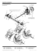
Apply loctite
& torque to
55 - 60
in-lbs.
Pack groove
with grease.
Apply locktite &
torque to 8 - 10 ft. lbs.
Inside of
frame.
Tighten when all parts
are tight against
shoulder of hub.
Torque to
10 - 14 ft-lbs.
Inside of frame.
Coat with Protectokote
or rust preventive oil.
Apply anti-seize
to both ends.
Bell crank must
pivot freely.
37
Flat side
toward bearing.
Earred
end
With hub (Ref. 32) away from pivot arm
assembly (Ref. 35), tighten so that drive disk
(Ref. 39) has no play, but will freely rotate.
Torque to
18 - 21 ft-lbs.
Remove all play out of axle by
moving axle to left, move set
collar (Ref. 27) to the right to take
all play out of sprocket assembly
(Ref. 29) and tighten. Befiore
making this adjustment be sure tie
bar support (see Frame Group) is
installed between frame sides.
18
TP-400-2001-05-IW-S
© Copyright 1999 Simplicity Manufacturing, Inc. All Rights Reserved.
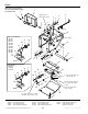
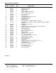
Traction Drive
NOTE: Unless noted otherwise,
use the standard hardware torque
specification chart.
The above parts group applies to the following Mfg. Nos.:
1692680 555M, 5HP Manual Start
1692681 755E, 7HP Electric Start
1692746 755M, 7HP Manual Start (Exp.)
1693161 555M, 5HP Manual Start
1693162 755E, 7HP Electric Start
1693163 555M, 5HP Manual Start (Exp.)
1693164 755M, 7HP Manual Start (Exp.)
1693425 555M, 5HP Manual Start
Continued on next page