
Snow Blower - Snow Thrower User Manual

1
2
3
3
4
1
2
3
3
5
6
7
8
9
10
11
12
13
14
15
16
17
18
19
20
21
22
22
10
23
24
25
26
27
28
29
30
31
32
33
34
35
36
37
38
39
40
41
31
32
31
38
42
43
44
45
46
47
48
49
50
51
52
53
17
3838
28
29
30
48
54
55
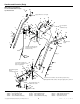
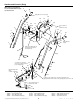
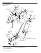
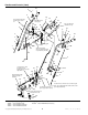
Apply adhesive to secure grip.
Ref. 18 required
on
slotted holes only.
Slot in support (Ref. 37)
towards rear of unit.
Mount bushings with
flange
on inside of brackets.
Shift rod assembly (Ref. 53)
must pivot freely on pivot
blocks (Ref. 48).
Apply adhesive
to grip.
Position in slots of frame to be sure hub of gear (Ref. 32) is
tight against the inside surface of the gear support (Ref. ) show 0 -2
Use washers to shim gear
(Ref. 32) as required to ensure
proper engagement.
31
2
TP-400-2001-05-IW-S
© Copyright 1999 Simplicity Manufacturing, Inc. All Rights Reserved.
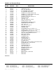
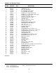
Handles and Controls (Early)
NOTE: Unless noted otherwise,
use the standard hardware torque
specification chart.
The above parts group applies to the following Mfg. Nos.:
1692680 555M, 5HP Manual Start
1692681 755E, 7HP Electric Start
1692746 755M, 7HP Manual Start (Exp.)
1633161 555M, 5HP Manual Start
1693162 755E, 7HP Electric Start
1693163 555M, 5HP Manual Start (Exp.)
1693164 755M, 7HP Manual Start (Exp.)
1693425 555M, 5HP Manual Start
1693426 755E, 7HP Electric Start