Print Vendor Instructions Paper Size: How to use this file Operator’s Manuals • 11x17 • Body - 50 lbs brilliant white offset or equivalent • Cover - on pre-printed two tone “Swash” stock. Press: • Body - 1 color, 2-sided • Cover - 1 color, 1 sided Bindery: • Saddle stitch, face trim *if too thick for saddle stitch, tape bind Covers: • FRONT COVER is present at the beginning of the file. • BACK COVER is the page immediately after the front cover.
THIS PAGE INTENTIONALLY BLANK (FOR PLACEMENT ONLY - DO NOT PRINT)
OPERATOR’S MANUAL Legacy / 2000 / 2900 Series 20HP Tractors 25HP Tractors Mfg. No. 1692870 1693114 1693124 1693132 1693219 1693220 1693221 1693250 Mfg. No.
MANUFACTURING, INC. 500 N Spring Street / PO Box 997 Port Washington, WI 53074-0997 www.simplicitymfg.com © Copyright 2003 Simplicity Manufacturing, Inc. All Rights Reserved. Printed in USA.
Table of Contents Safety Rules & Information.................................2 Identification Numbers........................................5 Troubleshooting, Adjustments & Service .......27 Troubleshooting the Tractor ..................................27 Troubleshooting the Mower ..................................28 PTO Clutch Adjustment ........................................29 Brake Linkage Adjustment ....................................29 Tractor PTO Belt Replacement .............................
Safety Rules & Information Read these safety rules and follow them closely. Failure to obey these rules could result in loss of control of unit, severe personal injury or death to you, or bystanders, or damage to property or equipment. This mowing deck is capable of amputating hands and feet and throwing objects. The triangle in text signifies important cautions or warnings which must be followed.
Safety Rules and Information SLOPE OPERATION WARNING Slopes are a major factor related to loss-of-control and tipover accidents, which can result in severe injury or death. All slopes require extra caution. If you cannot back up the slope or if you feel uneasy on it, do not operate on it. Control of a ride-on machine sliding on a slope will not be regained by the application of the brake.
Safety Rules & Information SERVICE AND MAINTENANCE • Grass catcher components are subject to wear, damage, and deterioration, which could expose moving parts or allow objects to be thrown. Frequently check components and replace with manufacturer’s recommended parts, when necessary. • Mower blades are sharp and can cut. Wrap the blade(s) or wear gloves, and use extra caution when servicing them. • Check brake operation frequently. Adjust and service as required.
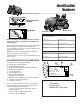
Identification Numbers SA M North American Models PL E 169XXXX SA Mfg. No.: 2002 dB(A) CE Models Mower ID Tag Tractor ID Tag M Serial No.: XXXXX kW: XXX Engine RPM XXXX LpA: XXX dB(A) Vibration @ Wheel: XXX m/s² Vibration @ Seat: XXX m/s² PL PRODUCT Simplicity Mfg. Inc. Port Washington, WI USA 53074-0997 REFERENCE DATA Model Description Name/Number E When contacting your authorized dealer for replacement parts, service, or information you MUST have these numbers.
Safety Rules & Information SAFETY DECALS All DANGER, WARNING, CAUTION and instructional messages on your rider and mower should be carefully read and obeyed. Personal bodily injury can result when these instructions are not followed. The information is for your safety and it is important! The safety decals below are on your rider and mower.
NOTES 7
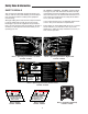
Features & Controls Please take a moment and familiarize yourself with the name, location, and function of these controls so that you will better understand the safety and operating instructions provided in this manual. B C D E F A G P H Q I Figure 1. Tractor & Mower Controls A. B. C. D. E. F. G. H. I. J. K. L. M. N. O. P. Q. R.
Features & Controls Control Functions continued… G. Ignition Switch N. Cruise Control The cruise control is used to set a constant FORWARD ground speed. This is useful when mowing long rows or traveling long distances. The ignition switch starts and stops the engine, it has three positions: NOTE: Never leave the ignition switch in the RUN position with the engine stopped–this drains the battery.
Features & Controls DASHBOARD DISPLAY FUNCTIONS Models with Air Cooled Engines The dashboard display shows a variety of engine operation and control status information, as explained in the descriptions below. A B C D E A. Rear PTO Light Indicates that the optional rear PTO switch is in the ON position. B. Cruise Control Light 18 14 Indicates that the cruise control is engaged. 8 C. Hour Meter Displays number of hours the unit has been operated. D.
Features & Controls SAFETY INTERLOCK SYSTEM This unit is equipped with safety interlock switches and other safety devices. These safety systems are present for your safety, do not attempt to bypass safety switches, and never tamper with safety devices. Check their operation regularly. Operational SAFETY Checks Your unit is equipped with a seat switch safety system. Check the seat switch operation every fall and spring with the following tests. Figure 4.
Operating the Tractor GENERAL OPERATING SAFETY WARNING Before first time operation: • Be sure to read all information in the Safety and Operation sections before attempting to operate this tractor and mower. Never allow passengers to ride on the unit. Before leaving the operator’s position for any reason, engage the parking brake, disengage the PTO, stop the engine and remove the key. • Become familiar with all of the controls and how to stop the unit.
Operating the Tractor WARNING STOPPING THE TRACTOR & ENGINE If you do not understand how a specific control functions, or have not yet thoroughly read the FEATURES & CONTROLS section, do so now. 1. Setting the cruise control to neutral and taking your foot off the ground speed control pedals will stop tractor movement. For emergency stopping depress the brake pedal. 2. Engage the parking brake. 3. Disengage the PTO. 4. Throttle the engine down to approximately 2200 RPM and turn the ignition key to OFF.
Operating the Tractor PUSHING & TOWING THE TRACTOR Moving the right control lever forward (C, Figure 7) will send pressurized hydraulic fluid to the far right quick connector. 1. Disengage the PTO and turn the engine off. 2. Shift the two speed control into neutral and release the parking brake. Moving the right control lever backward (D, Figure 7) will send pressurized hydraulic fluid to the right middle quick connector. The tractor can now be pushed by hand .
Operating the Tractor A B C Figure 8. Quick Connectors A. B. C. Figure 9. Install Quick Connector Covers Hoses Quick Connector Connector Covers Connecting Hydraulic Hoses Bumper Removed For Clarity The female quick connectors (B, Figure 8) require a 1/4” male nose piece fitting (part number 173359). Connect the hoses from the attachment hydraulic cylinders (A, Figure 8) to the quick connectors (B) located under the left foot rest.
Operating the Tractor MOWER DECK REMOVAL & INSTALLATION NOTE: Perform mower removal and installation on a hard, level surface such as a concrete floor. WARNING Engage parking brake, disengage PTO, stop engine and remove key before attempting to install or remove the mower. 54” Mower Removing the Mower Deck 1. Start the engine 2. Set the mower cutting height to minimum. 48” Mower & 60” Mower 3. Fully raise the attachment lift. 4. Stop the engine. 48” AND 60” MOWERS Figure 12.
Operating the Tractor Installing the Mower Deck 1. Raise the attachment lift and slide the mower under the tractor. 2. Hook up the electrical connection (Figure 15). 3. Start the engine. 4. Set the cutting height to maximum. 5. Fully lower the attachment lift. 6. Shut off the engine. 7. Make sure the mower lift chains are directly below the lift arms. Attach the 2 mower lift chains to the tractor lift arms (Figure 14). Figure 15. Mower Electrical Connection 8.
Operating the Tractor STORAGE WARNING • Battery life will be increased if it is removed, put in a cool, dry place and fully charged about once a month. If the battery is left in the unit, disconnect the negative cable. Never store the unit (with fuel) in an enclosed, poorly ventilated structure. Fuel vapors can travel to an ignition source (such as a furnace, water heater, etc.) and cause an explosion. Before starting the unit after it has been stored: • Check all fluid levels.
Regular Maintenance MAINTENANCE SCHEDULE & PROCEDURES The following schedule should be followed for normal care of your tractor and mower.
Regular Maintenance WARNING Gasoline is highly flammable and must be handled with care. Never fill the tank when the engine is still hot from recent operation. Do not allow open flame, smoking or matches in the area. Avoid over-filling and wipe up any spills. A B Do not remove fuel filter when engine is hot, as spilled gasoline may ignite. DO NOT spread hose clamps further than necessary. Ensure clamps grip hoses firmly over filter after installation.
Regular Maintenance 4. Allow the filter to drain until all water and debris have drained out. 5. Turn the base of the filter back to close the fuel filter valve when finished draining. E OIL & FILTER CHANGE D Refer to Figure 21, 23 & 24 for oil filter and dipstick locations. To drain the oil: A 1. Place a drain pan below the engine oil pan. 2. Remove the oil drain plug and allow the engine to completely drain. C B 3. Remove and replace the oil filter. 4. Reinstall the oil drain plug. Figure 22.
Regular Maintenance CHECK/CLEAN OIL COOLER (23HP MODELS ONLY) Bumper Removed For Clarity The oil cooler (G, Figure 21) should be cleaned every 25 hours, or as necessary. CHANGE ANTIFREEZE (LIQUID COOLED MODELS ONLY) See Engine Manual for specific antifreeze procedures. On Kawasaki models the antifreeze drain valve is located on the bottom of the radiator. On Diesel the antifreeze drain valve is located at the base of the left hand side of the radiator.
Regular Maintenance LUBRICATION Lubricate the unit at the locations shown in Figures 28 through 33 as well as the following lubrication points. Grease: • front axle grease fittings • steering linkage • foot pedal • mower pivots • mower arbors Use grease fittings when present. Disassemble parts to apply grease to moving parts when grease fittings are not installed. Not all greases are compatible.
Regular Maintenance Grease the Electric Lift Rod Grease Fitting Yearly Grease the Deck Belt Idler Pulley Arm Grease Fitting Yearly 48” Mower 60” Mower 54” Mower Figure 31. Deck Lubrication Every 10 Hours Figure 32. Mower Arbor Lubrication Figure 33.
Regular Maintenance BATTERY MAINTENANCE WARNING Checking the Battery Fluid Be careful when handling the battery. Avoid spilling electrolyte. Keep flames and sparks away from the battery. NOTE: This procedure does not apply to maintenance free batteries. 1. Raise the hood to access battery. When removing or installing battery cables, disconnect the negative cable FIRST and reconnect it LAST. If not done in this order, the positive terminal can be shorted to the frame by a tool. 2.
Regular Maintenance SERVICING THE MOWER BLADES WARNING For your personal safety, do not handle the sharp mower blades with bare hands. Careless or improper handling of blades may result in serious injury. 1. Remove mower from the tractor. See Mower Installation & Removal. 2. Blades should be sharp and free of nicks and dents. If not, sharpen blades as described in following steps. 3. To remove blade for sharpening, use a wood block to hold blade while removing the blade mounting capscrew (Figure 36).
Troubleshooting Adjustments & Service TROUBLESHOOTING WARNING While normal care and regular maintenance will extend the life of your equipment, prolonged or constant use may eventually require that service be performed to allow it to continue operating properly. To avoid serious injury, perform maintenance on the tractor or mower only when the engine is stopped and the parking brake engaged. The troubleshooting guide below lists the most common problems, their causes and remedies.
Troubleshooting, Adjustment & Service TRACTOR TROUBLESHOOTING CONTINUED PROBLEM Brake will not hold. Tractor steers hard. Low Oil Pressure Light is On Irregular Voltage Light is On. Or Volt Meter Indicates Irregular Voltage Level Differential Lock Won’t Engage Cruise Control Won’t Stay Engaged 2 Speed Control Won’t Shift CAUSE 1. Brake is incorrectly adjusted. 2. Brake worn out 1. Power steering Malfunction 2. Improper tire inflation. 3. Spindle bearings dry. 1.
Troubleshooting, Adjustment & Service PTO CLUTCH ADJUSTMENT WARNING Burnishing The Clutch To avoid serious injury, perform adjustments only with engine stopped, key removed and tractor on level ground. Before the front PTO clutch is used for the first time, it should be burnished as follows. To burnish the clutch, the mower must be installed. 1. Start the engine and set at full throttle. A A 2. Pull the front PTO switch out to the on position, leave for 15 seconds, then push in to the off position.
Troubleshooting, Adjustment & Service To avoid damaging belts, DO NOT PRY BELTS OVER PULLEYS. TRACTOR PTO BELT REPLACEMENT NOTE: The PTO belts are a matched set and must be replaced as a set. If the belts are being removed for inspection, make sure they are reinstalled in the their original pulley groove and rotational orientation. 1. Park the tractor on a level surface. Disengage the PTO, turn off the engine and set the parking brake. Remove the key. A 2. Tilt the hood forward. Figure 41.
Troubleshooting, Adjustment & Service MOWER ADJUSTMENTS WARNING Roller Bracket Adjustment (60” Mower Only) Before checking mower, shut off PTO and engine. Allow all moving parts to stop. Remove ignition key, then disconnect the spark plug wires and fasten them away from the spark plugs. The anti-scalping rollers (A, Figure 44) can be adjusted for different cutting heights by positioning roller brackets on the mower baffle (B). 1. Remove bolts, lockwashers and nuts securing roller bracket to baffle. 2.
Troubleshooting, Adjustment & Service Mower Adjustments Continued. WARNING Cutting Height Adjustment Before checking mower, shut off PTO and engine. Allow all moving parts to stop. Remove ignition key, then disconnect the spark plug wires and fasten them away from the spark plugs. Note: To operate the electric cutting height motor, it is necessary to insert the ignition key and turn it to the on position.
Troubleshooting, Adjustment & Service BELT ROUTING VIEWED FROM TOP To avoid damaging belts, DO NOT PRY BELTS OVER PULLEYS. Outer Pulley MOWER BELT REPLACEMENT Drive Pulley V Idler Outer Pulley Belt Double V 60” Mower Drive Belt Replacement V Idler 1. Remove the mower deck. See Mower Removal and Installation FRONT 2. Remove the screws securing both deck covers and remove the covers. Center Pulley Figure 49. 60” Mower Deck Belt Routing 3.
Troubleshooting, Adjustment & Service 54” Mower Drive Belt Replacement B 1. Remove the mower deck. See Mower Removal and Installation D C A 2. Remove the taptite screws (A, Figure 51) securing the belt covers and remove the belt covers (B, D). 3. Using a spring puller or a small rope loop, release the idler assembly tension spring (A, Figure 53). E 4. Remove the old drive belt. A 5. Inspect all pulleys for wear or bearing damage. 6.
Troubleshooting, Adjustment & Service 48” Mower Drive Belt Replacement BELT ROUTING VIEWED FROM TOP 1. Remove the mower deck. See Mower Removal and Installation FRONT Outer Pulley Outer Pulley 2. Remove the screws securing both deck covers and remove the covers. Drive Pulley 3. Using a spring puller or a small rope loop, release the idler assembly tension spring (A, Figure 55). V Idler Belt Double V 4. Remove the old belt. Center Pulley 5. Inspect all pulleys for wear or bearing damage.
Specifications NOTE: Specifications are correct at time of printing and are subject to change without notice.
Section Title TRANSMISSION - HYDRO DIMENSIONS Type Pump Motor Hydraulic Fluid Hydrostatic Sundstrand Model 15U Variable Displacement Axial Type Fixed Displacement Reversible Axial Type Type F Transmission Fluid Reservoir: 6 Qt. Capacity (5.
Parts & Accessories Replacement Parts Maintenance Items Tractor Drive Belt (Models w/Kohler engines) 1716996 Tractor Drive Belt (Models w/Kawasaki engines)1716995 PTO Drive Belt-Diesel (Qty.