How to use this file...(Operators Manuals) ————————————————————————————————————————————––– Instructions for Print Vendors (Paper Manuals) Paper Size: * 11 x 17 * Body—50 lbs brilliant white offset or equivalent. * Cover—on pre-printed two-tone “Swash” stock. Press: * Body—1-color, 2-sided * Cover imprint —1-color, 1-sided Bindery: * Saddle Stitch, Face Trim * Face Trim COVERS: * This file may contain several manuals, which differ only in their covers.
THIS PAGE INTENTIONALLY BLANK
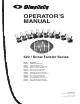
OPERATOR’S MANUAL 520 / Snow Tackler Series Mfg. No. 1692917 1692918 1692977 1692978 1692979 1692980 1692981 1692984 1692985 1692986 1692991 1692992 1693166 Description 520M, 5HP Snowthrower 520E, 5HP Snowthrower Green Bay Packers Snowthrower Minnesota Vikings Snowthrower Chicago Bears Snowthrower Detroit Lions Snowthrower Pittsburgh Steelers Snowthrower New England Patriots Snowthrower New York Jets Snowthrower St.
MANUFACTURING, INC. 500 N Spring Street / PO Box 997 Port Washington, WI 53074-0997 www.simplicitymfg.com © Copyright 2003, Simplicity Manufacturing, Inc. All Rights Reserved. Printed in USA.
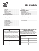
Table of Contents Regular Maintenance Removing Belt Cover ............................................12 Lubrication ............................................................12 Troubleshooting & Service Troubleshooting ....................................................13 Removing Engine Cover .......................................13 Auger Control Cable Adjustment ..........................14 Carburetor Adjustment (Ref. only) ........................14 Replacing the Drive Belt .........................
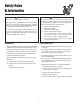
Safety Rules & Information WARNING WARNING This unit is a “single-stage” snowthrower. To avoid serious injury, do not put your hands into the auger housing or discharge chute. If auger stalls or chute becomes plugged, use the following procedure to remove objects or clear the chute: The auger feeds the snow back into the housing and throws the snow out the discharge chute. If bodily contact is made with the auger or impeller when they are rotating, severe personal injury will occur. 1. 2. 3. 4. 5.
Safety Rules & Information OPERATION MAINTENANCE & STORAGE • Keep hands and feet away from rotating parts. Keep clear of discharge opening at all times. • Keep all nuts, bolts and screws tight to ensure that the equipment is in safe operating condition. • Always clear snow up and down the face of slopes, never across the face. Use extreme caution when changing direction on slopes. Do not attempt to clear slopes over 17.7% (10o).
Safety Rules & Information SAFETY DECALS Safety warning decals are placed at strategic locations on the snowthrower as a constant reminder to the operator of the most important safety precautions. All warning, caution and instructional messages on your snowthrower should be carefully read and obeyed. If any of these decals are lost or damaged, replace them at once. They can be purchased from your local dealer. Part No. 1716672 Auger Control Decal Part No.
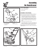
Assembling the Snowthrower TOOLS REQUIRED • Socket or Wrench Set A • Pair of Pliers ASSEMBLY PROCEDURE C If your unit was not previously assembled, see Figures 1 and 2, and follow the steps below to assemble the unit: D 1. Install the discharge chute on to the rotating ring located on the auger housing. Secure with the three 5/16 inch carriage bolts, flat washers and nylok nuts found in the parts bag (the bolt heads go to inside of of the rotating ring, with washers and nuts on the outside).
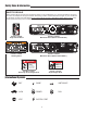
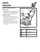
Controls & Operation SNOWTHROWER CONTROLS A Auger Control C A. Auger Control - This control engages and disengages the auger. Pull the control back against handle to engage the auger, (this will pull snowthrower forward if auger is in contact with the ground). Release the Auger Control to stop rotation of auger. B Deflector Controls B. Chute Direction Control - The Chute Direction Control (B, Figure 4) allows the discharge chute to be rotated to throw snow in the desired direction.
Controls & Operation ENGINE & STARTING CONTROLS C NOTE: Throttle - This snow thrower does NOT have a throttle for controlling operating speed of engine. The engine governor maintains operating speed for varying snow removal conditions. B Electric Start Units Only A. Electric Start Button - The Electric Start Button (A, Figure 5) activates an electric starter mounted to the engine, eliminating the need to pull the starter handle.
Controls & Operation GENERAL OPERATION CHECKS BEFORE EACH START-UP WARNING 1. Make sure all safety guards are in place and all nuts, bolts and clips are secure. To avoid serious injury, do not put your hands into the auger housing or discharge chute. If auger stalls or chute becomes plugged, use the following procedure to remove objects or clear the chute: 2. Check the fuel supply. Fill the tank no closer than 1/4 to 1/2 inch of top of tank to provide space for expansion.
Controls & Operation FUEL AND OIL MIXTURE FUEL TO OIL MIXTURE CHART (50:1) U.S. The snowthrower uses a two cycle engine that requires a mixture of fuel (gasoline) and oil for lubrication of engine bearings and other moving parts. Imperial Metric Gasoline 2 Cycle Oil Gasoline 2 Cycle Oil Gasoline 2 Cycle Oil Gallons Ounces Gallons Ounces Liters Milliliters The correct fuel/oil mixture ratio for the five horsepower engine is 50 to 1. Use fuel/oil mixture chart shown.
Controls & Operation STARTING THE ENGINE DANGER NOTE: The snow thrower engine is designed to operate at cold temperatures. Avoid operating the snow thrower if air temperature is 40° C or warmer since engine may vapor lock and stop running after a short time. Engine will be difficult to start in warm weather. Never run engine indoors or in enclosed, poorly ventilated areas. Engine exhaust contains CARBON MONOXIDE, an ODORLESS and DEADLY GAS.
Controls & Operation OPERATING THE SNOWTHROWER OFF-SEASON STORAGE Before operating snowthrower, review the Checks Before Each Use under General Operation on page 8 of this manual.
Regular Maintenance Removing Belt Cover In order to perform proper lubrication, it is necessary to remove the Belt cover from the lower left of the snowthrower. Screws 1. Remove the Engine Key from the switch. 2. Remove the fours screws securing the belt cover (see Figure 7). 3. Remove the cover. Figure 7. Removing Belt Cover 4. Perform lubrication (see below). 5. Reinstall belt cover (reverse steps 3 to 1 above.
Troubleshooting & Service TROUBLESHOOTING Problem Possible Cause Remedy Engine fails to start 1. Key is OFF 2. Failure to prime cold engine 3. Out of fuel 4. Choke OFF - cold engine 5. Engine flooded 6. Spark Plug not sparking 1. Turn Key to the ON position 2. Press primer button twice and restart. 3. Fill fuel tank 4. Turn Choke to ON. 5. Turn Choke to OFF; try starting 6. Check Gap. Gap plug, clean electrode, or replace as necessary 7. Drain tank (Dispose of fuel at an authorized waste facility).
Troubleshooting & Service Lift Cover from Rear of unit Locknuts Spring Insert front tabs first when reinstalling cover. Align rear tabs & side of cover when reinstalling. Figure 12. Cover Removal & Installation Figure 13. Auger Control Cable AUGER CONTROL CABLE ADJUSTMENT Adjusting the Cable The length of the auger control cable is adjustable.
Troubleshooting & Service REPLACING THE DRIVE BELT 1. Remove Engine Key from switch. 2. Remove belt and engine covers. Idler Pulley 3. Move the Auger Control on the handle and slip the belt out from between the brake lever and roller and away from the idler pulley. Engine Pulley 4. Remove the belt from the engine and auger pulleys. 5. Install new belt around engine and auger pulleys and under idler pulley. The ribbed side of the belt must be to the inside, against auger and engine pulleys. 6.
Specifications Parts & Accessories ENGINE Make & Model . . . . . Tecumseh HSK 850, Two Cycle, Single cylinder, horizontal crankshaft, aluminum alloy with cast iron sleeve Horsepower . . . . . . . 5HP @ 4000 RPM Bore . . . . . . . . . . . . . 2.44 in (61.9 mm) Stroke. . . . . . . . . . . . 1.81 in (46.0 mm) Displacement . . . . . . 8.46 cu in (139 cc) Ignition . . . . . . . . . . . Capacitor Discharge Electronic Choke. . . . . . . . . . . . Combination primer & Choke Fuel Capacity . . . . . . 2.4 qts. (2.