How to use this file...(Operators Manuals) ————————————————————————————————————————————––– Instructions for Print Vendors (Paper Manuals) Paper Size: * 11 x 17 * Body—50 lbs brilliant white offset or equivalent. * Cover—on pre-printed two-tone “Swash” stock. Press: * Body—1-color, 2-sided * Cover imprint —1-color, 1-sided Bindery: * Saddle Stitch, Face Trim * Face Trim COVERS: * This file contains several manuals, which differ only in their covers.
THIS PAGE INTENTIONALLY BLANK
OPERATOR’S MANUAL Intermediate Snowthrower Models 555 Models Mfg. No. 1693646 1693647 Description 555M, 5HP Snowthrower, Manual Start 555M, 5HP Snowthrower, Manual Start (Export) 755 Models Mfg. No.
MANUFACTURING, INC. 500 N Spring Street / PO Box 997 Port Washington, WI 53074-0997 www.simplicitymfg.com © Copyright 1999, Simplicity Manufacturing, Inc. All Rights Reserved. Printed in USA.
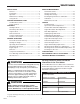
Table Of Contents SAFETY RULES General ...................................................................2 Preparation .............................................................2 Operation ................................................................3 Maintenance & Storage ..........................................3 Safety Decals ..........................................................4 CONTROL REFERENCE CHART Snowthrower Controls.............................................5 Engine Controls ......
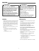
Safety Rules WARNING WARNING This unit is a “two-stage” snowthrower. To avoid serious injury, do not put your hands into the auger housing or discharge chute. If auger stalls or chute becomes plugged, use the following procedure to remove objects or clear the chute: 1. Release both the Drive and Auger Control levers. 2. Shut off the engine. 3. Remove the Engine Key. 4. Wait for moving parts to stop. 5. Disconnect spark plug wire. 6.
Safety Rules OPERATION MAINTENANCE & STORAGE • Keep hands and feet away from rotating parts. Keep clear of discharge opening at all times. • Keep all nuts, bolts and screws tight to ensure that the equipment is in safe operating condition. • Always clear snow up and down the face of slopes, never across the face. Use extreme caution when changing direction on slopes. Do not attempt to clear slopes over 17.7% (10o).
Safety Signs & Decals SAFETY DECALS Safety warning decals are placed at strategic locations on the snowthrower as a constant reminder to the operator of the most important safety precautions. All warning, caution and instructional messages on your snowthrower should be carefully read and obeyed. If any of these decals are lost or damaged, replace them at once. They can be purchased from your local dealer. WARNING TO AVOID SERIOUS INJURY • Read Owner’s Manual before operating unit.
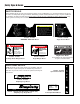
Control Reference Chart SNOWTHROWER CONTROLS A Speed Selector Selects Forward Speeds 1 - 5, Reverse Speeds 1 - 2 B Drive Control Engages drive to wheels as it is depressed; disengages when released. C Auger Control D A B C E Engages auger/impeller as it is depressed; disengages when released. F H D Chute Direction Control Rotates discharge chute to desired direction E Chute Deflector Controls vertical angle snow is thrown.
Controls STARTING CONTROLS A B Units with Optional Electric Start A. Electric Start Button - The Electric Start Button (A, Figures 4 & 5) activates an electric starter mounted to the engine, eliminating the need to pull the starter handle. The Electric Start Button operates on 120 Volts AC, which is provided by connection to the extension cord provided with units equipped with this feature. Connect this extension cord ONLY to a properly grounded 3 prong electrical outlet. C Manual Start B.
Controls GROUND SPEED CONTROLS C A. Speed Selector - This lever (A, Figures 6 & 7) is used to set the ground speed of the snowthrower. A B D The snowthrower has five forward speeds, 1–5, and two reverse speeds, 1–2. No neutral position or gate is required, since the traction drive design automatically provides "neutral" (no forward or reverse movement), whenever the Drive Control is released. B.
Operation GENERAL OPERATION WARNING To avoid serious injury, do not put your hands into the auger housing or discharge chute. If auger stalls or chute becomes plugged, use the following procedure to remove objects or clear the chute: CHECKS BEFORE EACH START-UP 1. Make sure all safety guards are in place and all nuts, bolts and clips are secure. 2. Check the engine oil level. See your engine Owner’s Manual for procedure and specifications. 1. Release both the Drive and Auger Control levers. 2.
Operation STARTING THE ENGINE A B 1. Turn the fuel valve (B, Figures 8 & 9) to the ON position. C 2. Insert the Engine Key (F, Figures 8 & 9) into the Engine Key slot and push fully in to the RUN position. 3. Move the Throttle Lever (E, Figures 8 & 9) fully up to the FAST position. 4. Fully close the Choke (G, Figures 8 & 9) if engine is cold. (Do not choke a warm engine.) 5. Push the Primer Button (D, Figures 8 & 9) two times if engine is cold. (Do not prime a warm engine.) 6.
Operation OPERATING THE SNOWTHROWER C 1. Rotate the discharge chute to the desired direction. A B D 2. Set the Speed Selector to the desired forward speed. 3. Fully press and hold the Auger Control (C, Figure 10) on the right-hand grip to begin auger rotation. To disengage the auger, completely release the lever. 4. Fully press and hold the traction Drive Control lever (B, Figure 10) on the left-hand grip to engage the traction drive and begin moving the snowthrower.
Operation DEFLECTOR Chute Deflector Knob The distance of the discharged snow is mainly controlled by the position of the deflector (Figure 12). (Engine speed also affects distance of discharge.) The more the deflector is tilted UP, the farther snow will be thrown. Loosen the deflector knob, tilt the deflector UP or DOWN, and then retighten the knob when the desired angle has been chosen. Chute Deflector Figure 12.
Operation FREE-WHEELING AND TRACTION DRIVE LOCK For easy turning when pushing the snowthrower, you can disengage the traction drive at one or both wheels by using the Traction Lock Pins (See Figures 14 & 15.) 1. Turn the unit off, remove the Engine Key, and disconnect the spark plug wire. Klik-Pin In OUTER Hole 2. To DISENGAGE the traction drive lock, insert the Traction Lock Pin through the outer hole in the axle. (See Figure 14). 3.
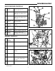
Regular Maintenance NORMAL CARE CARE REQUIRED FREQUENCY LUBRICATION Check auger gear case lubrication.** 25 Hours Simplicity Winter Weight Worm Gear Oil Lubricate snowthrower. 10 Hours 10W Oil and Grease Check tire pressure. Monthly N/A Change engine oil.*✛ 50 Hours✛ See Engine Manual Yearly See Engine Manual 4-6 Hours N/A Clean or replace spark plug.✛ Check drive linkage/belt tension * Change original oil after two hours of operation. ** Check oil level each fall and spring.
Regular Maintenance LUBRICATION IMPORTANT NOTE It is very important that grease fittings on the auger shaft are lubricated regularly. If auger rusts to shaft, damage to worm gear may occur if shear pins do not break. To prevent wheels rusting to axles, it is also necessary to remove the wheels and grease the axles regularly. There are two grease fittings on the auger shaft (Figure 18). Wipe the fittings clean and apply grease, using a grease gun. Also apply grease on other points indicated.
Regular Maintenance MAINTENANCE RECORDS: 01 15
Service TROUBLESHOOTING WARNING Before performing any adjustment or service to snowthrower, stop the engine and wait for moving parts to stop. Remove the key. To prevent accidental starting, disconnect the spark plug wire and fasten away from the plug. This section provides troubleshooting and service instructions. Locate the problem and check the possible cause/remedy in the order listed. Also, refer to the engine manufacturer’s Owner’s Manual for additional information.
Service PROBLEM POSSIBLE CAUSE REMEDY 1. Chute deflector too low. 1. Adjust deflector as necessary. 2. Engine speed too slow. 2. Set speed to full throttle. 3. Ground speed too fast. 4. Snowthrower discharge chute clogged. 3. Use slower Speed Selector setting. 4. STOP engine and REMOVE the key. DISCONNECT the spark plug wire. Clear auger using a narrow board. See warning in SAFETY RULES. 5. Auger belt loose or worn. 5. Check Auger Drive Belt Adjustment Scraper bar does not clean hard surface. 1.
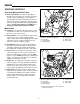
Service SPEED SELECTOR PIVOT ADJUSTMENT The Speed Selector is factory set for optimal performance at each forward and reverse speed setting. However, if drive system components have been replaced, adjustment may be necessary. A Adjust as follows: 1. Move the ground speed control (A, Figure 20) fully forward. 2. Loosen the hardware (B) securing the upper and lower shift rods. B 3. Push the lower rod (C) down fully (into the housing). 4.
Service AUGER DRIVE CLUTCH ROD ADJUSTMENT The auger drive clutch rod should be adjusted so that there is no slack in the rod when moved slightly from side to side. To adjust tension on the rod: Auger Drive Clutch Rod 1. Loosen adjustment hex nuts (Figure 22). 2. Tighten top hex nut while holding rod. Tighten just until slack in rod is removed. Be careful not to move idler rod lever when adjusting clutch rod tension. 3. Tighten lower hex nut securely.
Service DRIVE BELT ADJUSTMENT (Continued) If the auger drive slips (auger slows or doesn't rotate normally while blowing snow), or stays engaged when the control is disengaged — and the auger clutch rod has been properly adjusted — the auger drive belt may be out of adjustment. Auger Control Belt Cover WARNING Auger must NOT rotate unless the Auger Control lever has been depressed. Proper Auger Drive Belt adjustments stop the auger within 5 seconds after the Auger Control is disengaged. Figure 24.
Service DRIVE BELT ADJUSTMENT (Continued) WARNING Adjusting Auger Belt Guide Failure to properly adjust the Auger Belt Guide may cause auger to rotate when Auger Control has not been depressed. 1. With the Auger Control still fully depressed, adjust the Auger Belt Guide so that there is a 1/64” gap (1/32” Maximum) between the end of the guide and the belt (Figure 27), making certain the guide is NOT putting pressure on the belt. 2.
Service DRIVE BELT REPLACEMENT (Cont.) WARNING Auger Drive Belt Replacement Do not go near the discharge chute or auger when the engine is running. Do not run the engine with any cover or guard removed. 1. Remove gas from fuel tank and run engine until it stops running from lack of fuel. 2. Disconnect spark plug wire and fasten it away from the spark plug. Auger Drive Pulley 3. Remove belt cover (See Figure 27). 4. Loosen auger belt guide and slide belt off engine pulley and away from idler pulley.
Service ROLLER CHAIN REPLACEMENT NOTE: This procedure does not apply to models that use an “endless” chain. 1. Remove gas from fuel tank and run engine until it stops running from lack of fuel. 2. Disconnect spark plug wire and fasten it away from the spark plug. 3. Tilt the snowthrower forward and carefully rest unit on the auger end. 4. Rotate the wheel to locate the roller chain master link. 5. Remove the keeper link, master link and chain. 6. Install new chain and master link as shown in Figure 30. 7.
Service DISCHARGE CHUTE WORM ASSEMBLY ADJUSTMENT Discharge Chute If the Discharge Chute becomes difficult to rotate or begins to operate erratically, the Worm Assembly may require adjustment: Discharge Chute Worm Assembly 1. Loosen the adjustment screw under the Worm Assembly mounting area (Figure 33). 2. Slide the Worm Assembly in or out to provide smooth engagement between the worm wire and the slots in the base of the Discharge Chute. 3.
Specifications ENGINE AUGER HOUSING Make ................................................................Tecumseh Construction..............................Welded steel stampings Cylinders........................................................................1 Effective Width ..........................................22 in. (55 cm) Cycles.............................................................................4 Auger Opening Height with Extension........................................16.5 in.
Replacement Parts & Accessories COMMON REPLACEMENT PARTS ACCESSORIES Listed below are part numbers for the more common replacement parts. Use only genuine Simplicity replacement parts to assure optimum performance and safety. See your dealer to purchase any of the following accessories for your snowthrower. Simplicity Gas Stabilizer - 8 oz. Bottle ........................................................1685748 - Case of 12 Bottles (8 oz. ea.) ...........................