Print Vendor Instructions Paper Size: How to use this file Operator’s Manuals • 11x17 • Body - 50 lbs brilliant white offset or equivalent • Cover - on pre-printed two tone “Swash” stock. Press: • Body - 1 color, 2-sided • Cover - 1 color, 1 sided Bindery: • Saddle stitch, face trim *if too thick for saddle stitch, tape bind Covers: • FRONT COVER is present at the beginning of the file. • BACK COVER is the page immediately after the front cover.
THIS PAGE INTENTIONALLY BLANK (FOR PLACEMENT ONLY - DO NOT PRINT)
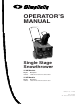
OPERATOR’S MANUAL Single Stage Snowthrower 319M Models Mfg. No. 1694382 Description 319M, 3HP Snowthrower, Manual Start 319E Models Mfg. No. 1694383 Description 319E, 3HP Snowthrower, Electric Start Manual No.
MANUFACTURING, INC. 500 N Spring Street / PO Box 997 Port Washington, WI 53074-0997 www.simplicitymfg.com © Copyright 2003, Simplicity Manufacturing, Inc. All Rights Reserved. Printed in USA.
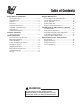
Table of Contents Safety Rules & Information Regular Maintenance General Operation ..................................................2 Slope Operation ......................................................2 Children...................................................................3 Emissions................................................................3 Service & Maintenance ...........................................3 ANSI B71.3-1995 Warnings ....................................4 Safety Decals .......
Safety Rules & Information Read these safety rules and follow them closely. Failure to obey these rules could result in loss of control of unit, severe personal injury or death to you, or bystanders, or damage to property or equipment. The triangle in text signifies important cautions or warnings which must be followed. GENERAL OPERATION • Read, understand, and follow all instructions in the manual and on the unit before starting.
Safety Rules EMISSIONS CHILDREN • Engine exhaust from this product contains chemicals known, in certain quantities, to cause cancer, birth defects, or other reproductive harm. • Look for the relevant Emissions Durability Period and Air Index information on the engine emissions label. Tragic accidents can occur if the operator is not alert to the presence of children. Children are often attracted to the unit and the operating activity. Never assume that children will remain where you last saw them.
Safety Rules ANSI B71.3-1995 WARNINGS Training 1. Read the operating and service instruction manual carefully. Be thoroughly familiar with the controls and the proper use of the equipment. Know how to stop the unit and disengage the controls quickly. 2. Never allow children to operate the equipment. Never allow adults to operate the equipment without proper instruction. 3. Keep the area of operation clear of all persons, particularly small children and pets. 4.
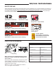
Safety Decals / Identification Numbers SAFETY DECALS Safety warning decals are placed at strategic locations on the snowthrower as a constant reminder to the operator of the most important safety precautions. All warning, caution and instructional messages on your snowthrower should be carefully read and obeyed. If any of these decals are lost or damaged, replace them at once. They can be purchased from your local dealer. 7028315 Part No. 7028315 Control Decal - Primer, Key Part No.
Features & Controls All Models Electric Start Models CONTROL LOCATIONS The information below briefly describes the function of individual controls. Starting, stopping, and driving require the combined use of several controls applied in specific sequences. To learn what combination and sequence of controls to use for various tasks see the OPERATION section. NOTE: Throttle - This snowthrower does NOT have a throttle for controlling operating speed of engine.
Features & Controls Chute Deflector Control Ignition Switch Controls the distance snow is thrown. Tilting the Chute Deflector UP provides a higher stream and greater distance, while tilting the deflector DOWN provides a lower stream and less distance. Loosen the deflector knob, adjust the deflector, then retighten the knob. The ignition switch starts and stops the engine, and can be removed to prevent engine starting.
Operation WARNING GENERAL OPERATION OPERATIONAL WARNINGS CHECKS BEFORE EACH START-UP Clearing The Discharge Chute 1. Make sure all safety guards are in place and all nuts, bolts and clips are secure. 4. Check the Chute Direction Control for proper operation. The discharge chute should rotate freely in both directions. See the Service section for adjustment procedures and troubleshooting. To avoid serious injury, do not put your hands into the auger housing or discharge chute.
Operation FUEL AND OIL MIXTURE WARNING The snowthrower uses a two cycle engine that requires a mixture of fuel (gasoline) and oil for lubrication of engine bearings and other moving parts. Gasoline is highly flammable and must be handled with care. Follow these fuel handling precautions: The correct fuel/oil mixture ratio is 50 to 1. Use fuel/oil mixture chart shown. • Use an approved fuel container.
Operation STARTING THE ENGINE B A NOTE: The snowthrower engine is designed to operate at cold temperatures. Avoid operating the snowthrower if air temperature is 40° F or warmer. Engine will be difficult to start in warm weather. WARNING Electric start precautions: • Use only with a polarized 120V AC outlet. Do not modify the plug to fit into any other type of outlet. • Use only the power cord supplied with the unit. DO NOT use a damaged cord.
Operation OPERATING THE SNOWTHROWER SNOWTHROWING TIPS Before operating snowthrower, review the CHECKS BEFORE EACH START UP on page 8 of this manual. Refer to FEATURES & CONTROLS for control locations. Discharge chute plugging may occur as the result of snow build up inside the chute. DO NOT use your hands to clear the blockage. DO NOT place your hands near the auger or discharge chute any time the engine is running.
Regular Maintenance MAINTENANCE SCHEDULE MAINTENANCE ITEMS Before Each Use Check Auger Cable & Stopping Time Check Auger & Flite Shoes Every 25 Hours Every 100 Hours Each Season • • • Check/Adjust Drive Belt** • • Clean Cooling Fins * • • Inspect Spark Plug * Replace Fuel Filter * Refer to the Engine Manufacturer’s Owner’s Manual for engine-related information. ** Adjust after the first 5 hours of operation. CHECK AUGER CABLE & STOPPING TIME A 1.
Troubleshooting, Adjustments, & Service TROUBLESHOOTING PROBLEM PROBABLE CAUSE CORRECTIVE ACTION Engine Will Not Start Using Recoil Starter 1. Fuel tank empty. 1. Fill fuel tank with fresh fuel/oil mix. 2. Engine needs choking & priming. 2. Move choke control to "CHOKE" position. Push primer bulb three times. 3. Spark plug fouled or wire disconnected. 3. Replace spark plug. Attach plug wire onto spark plug. Engine Will Not Crank 1.
Troubleshooting, Adjustments, & Service WARNING 5 Before beginning any repair stop the engine, remove the key, disconnect the spark plug wire, and wait for all moving parts to stop. 4 3 2 1 AUGER CONTROL ADJUSTMENT Inspection B 1. Inspect the auger cable for kinks, wear, or frayed cable strands. Replace if worn or damaged. A 2. Start the engine. 3. Engage the auger control for 5 seconds. Figure 5. Auger Cable Adjustment - Disengaged A. Cable Spring B. Jam Nut 4. Disengage the auger control.
Troubleshooting, Adjustments, & Service AUGER DRIVE BELT IDLER PULLEY ADJUSTMENT A If the auger control cable has run out of adjustment, the drive belt idler pulley (B) can be adjusted to take up more belt slack. B C D 1. Turn the engine OFF. 2. Loosen the jam nut (B, Figure 5) at the upper end of the cable. Hold the threaded end of the cable and turn the cable counterclockwise until the adjustment is half way between fully in and fully out. 3.
Troubleshooting, Adjustments, & Service A OFF OFF A Figure 9. Drive Belt Bracket A. Spring-Loaded Idler Pulley Figure 8. Drive Belt A. Belt Guide AUGER DRIVE BELT REPLACEMENT Equal Clearance Inspect belt frequently for signs of excessive wear. Visually check for cracking, fraying, severed or exposed belt strands. B C A 1. Remove the side belt cover (D, Figure 3). 2. Remove both belt cover retaining studs (D, Figure 7). Equal Clearance 3. Remove belt guide (A, Figure 8) 4.
Troubleshooting, Adjustments, & Service AUGER FLITE SHOE REPLACEMENT A Inspect the flite shoes frequently for signs of excessive wear. Visually check flite shoes for cracking, fraying, and severed or exposed belts. B 1. Turn the engine OFF, remove the key, disconnect the spark plug wire, and wait for all moving parts to stop. 2. Tilt the unit backward to access the auger. Secure the unit in the tilted position. 3. Remove all the self-tapping screws (C, Figure 11) securing the flite shoes to the auger.
Specification, Parts, & Accessories SPECIFICATIONS TECHNICAL MANUALS Engine Additional copies of this manual are available, as well as fully illustrated parts lists. These manuals show all of the product’s components in exploded views (3D illustrations which show the relationship of parts and how they go together) as well as part numbers and quantities used. Important assembly notes and and torque values are also included.